
A non-linear optical effect demonstration device
A nonlinear optics and demonstration device technology, applied in the field of nonlinear optics, can solve the problems of inability to adjust the intersecting area or volume, inability to adjust the laser angle, inconvenient use, etc. Effect
Patent Information
- Authority / Receiving Office
- CN · China
- Patent Type
- Patents(China)
- Current Assignee / Owner
- Publication Date
- 2021-06-11
Smart Images
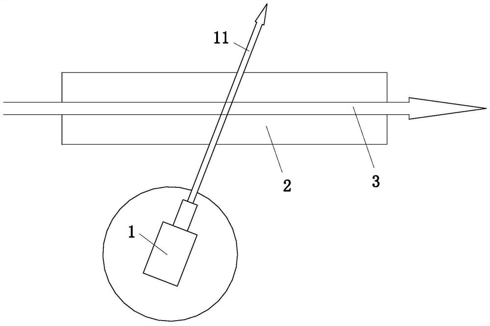
Figure 1 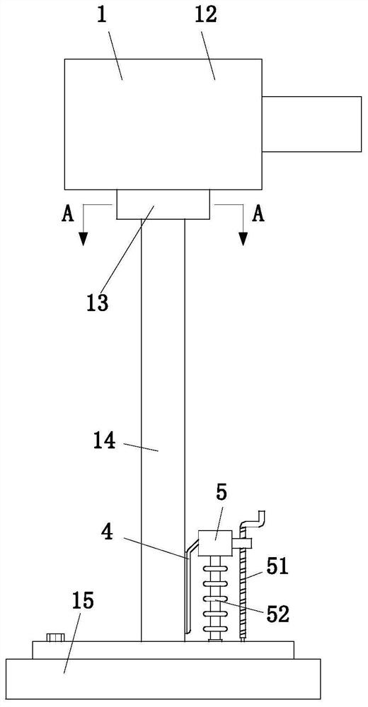
Figure 2 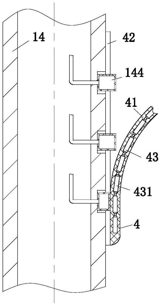
Figure 3
Abstract
Description
technical field
[0001] The invention belongs to the technical field of nonlinear optics, in particular to a nonlinear optical effect demonstration device. Background technique
[0002] A branch of modern optics, which studies the nonlinear phenomena and applications of media under the action of strong coherent light. The study of nonlinear optics is of great significance to the development of laser technology, spectroscopy, and material structure analysis. Commonly used second-order nonlinear optical crystals include potassium dihydrogen phosphate (KDP), ammonium dihydrogen phosphate (ADP), potassium dideuterium phosphate (KD*P), barium sodium niobate, etc. In addition, many third-order nonlinear optical materials have been discovered.
[0003] There are also some technical solutions for nonlinear optical demonstrations in the prior art. For example, a Chinese patent with application number 2013101883074 discloses a nonlinear optical effect device, including laser stacks, ...
Examples
Embodiment Construction
[0024] In order to make the technical means, creative features, goals and effects achieved by the present invention easy to understand, the present invention will be further described below in conjunction with specific embodiments.
[0025] Such as Figure 1 to Figure 6 As shown, a nonlinear optical effect demonstration device includes a laser generating module 1 and a medium 2; the second laser beam 3 is injected into the medium 2 in parallel; the laser generating module 1 includes a laser generator 12, a connection plate 13 , a support base 14 and a stable base 15; the laser generator 12 is installed on the top of the connection plate 13; Turn the torsion spring, and the inner wall of the connection plate 13 is fixedly connected to the baffle plate 131; the bottom end of the support base 14 is rotationally connected with the stable base 15, and a locking bolt is arranged between the support base 14 and the stable base 15, and the top of the support base 14 A group of right-...