
Vector control position estimation compensation method based on Hall position sensor
A Hall position and compensation method technology, applied in the direction of torque ripple control, electronic commutator, etc., can solve problems such as installation accuracy errors, achieve compensation of installation position deviation, compensation of position angle distortion, reduction of torque ripple and noise effect
Patent Information
- Authority / Receiving Office
- CN · China
- Current Assignee / Owner
- Publication Date
- 2019-10-25
Smart Images
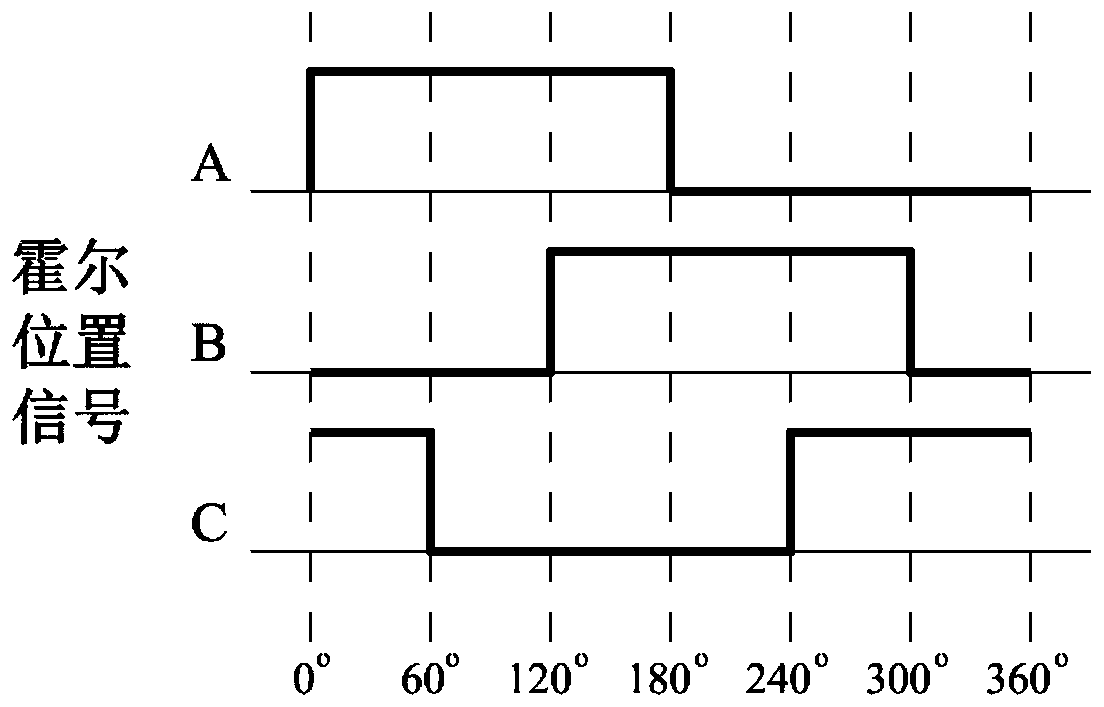
Figure 1 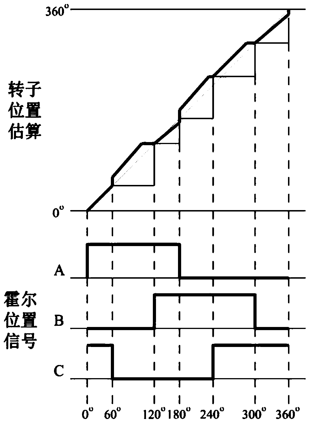
Figure 2 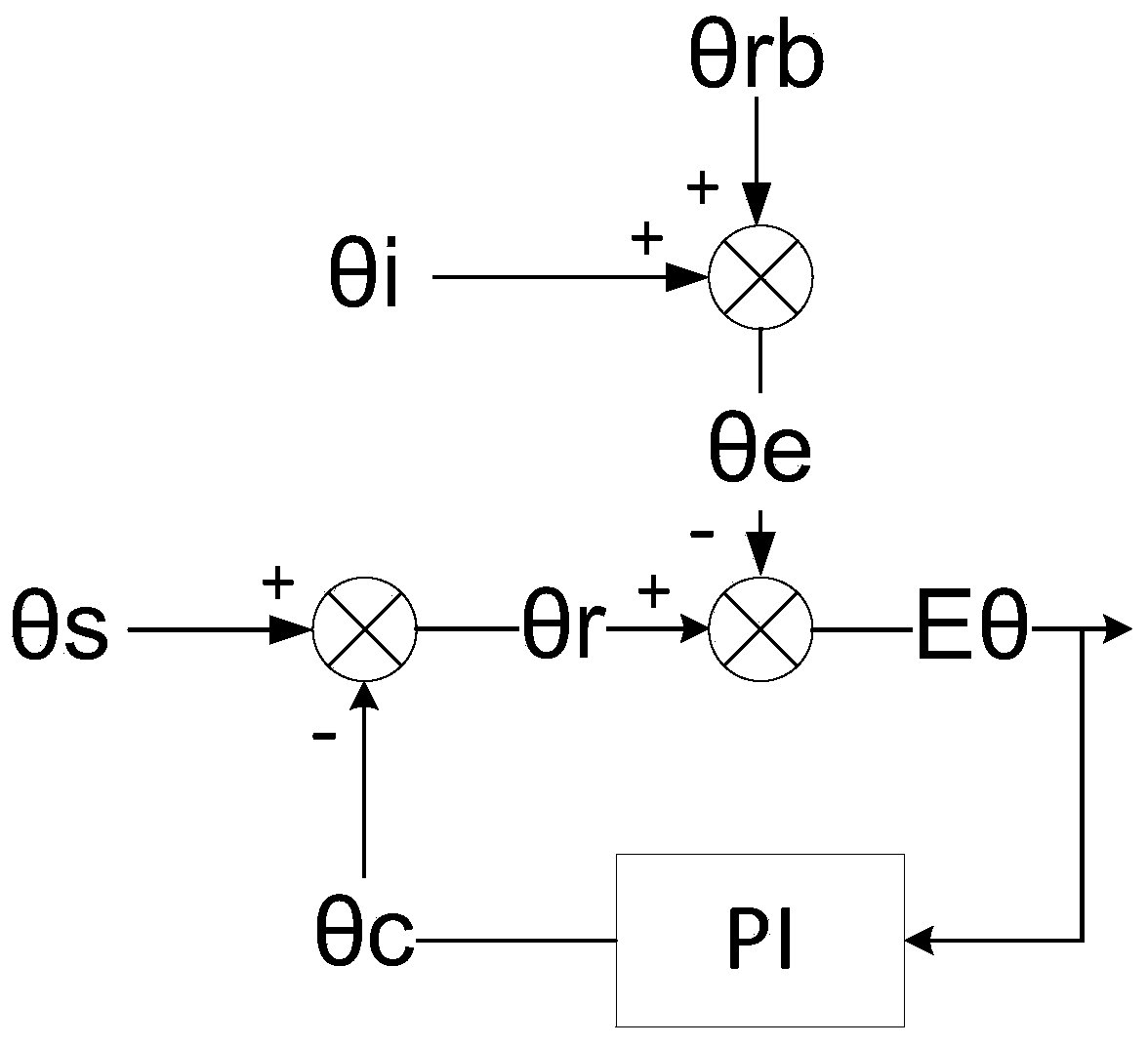
Figure 3
Abstract
Description
Technical field:
[0001] The invention belongs to the technical field of motor control, in particular to a method for estimating and compensating the position of a permanent magnet synchronous motor based on a Hall position sensor. Background technique:
[0002] Commonly used rotor position sensors for permanent magnet synchronous motors include resolvers, quadrature encoders, and Hall position sensors. Among them, the resolver and quadrature encoder have the advantages of high precision, but need to install additional equipment on the motor; the Hall sensor can be directly installed inside the motor, which is simple and convenient, but the disadvantage is low precision. The three-phase position signal provided by the three-phase Hall position sensor is as follows: figure 1 As shown, when the rotor rotates at a constant speed, the Hall position sensor provides three square wave signals with a duty cycle of 50% and a phase difference of 120°. The rising and falling edges of ...
Examples
Embodiment example
[0060] When the second jump edge is detected, according to the state change of the Hall sensor, it is judged that the motor is rotating forward, and the corresponding rotor angle θr=θs is 0°. Set the current position as the initial angle θrb of the first sector, and the initial angle is 0°. And the time interval between two jump edges is T, then when running in the first sector for t time, the estimated rotor angle θe=θrb+θi, that is, θe=0°+60*t / T.
[0061] When the third jump edge is detected, enter the second sector. According to the Hall state, the uncompensated installation angle θs=60° and the compensation value θc=0° of the second sector are obtained, then θr=θs-θc= 60°. And the total running time of the first sector is 0.9T, the estimated value of the initial angle of the second sector is θe=0°+60*0.9T / T=54°, then Eθ=θr-θe=6°. Assuming Ki=0.1, then θc=θc+Eθ*Ki=0.6°, then θs will also be used as the initial angle θb of the current sector at this time, that is, θb=60°. ...