
Diesel engine high-pressure fuel control booster pump
A high-pressure fuel and booster pump technology, applied in fuel injection pumps, mechanical equipment, engine components, etc., can solve the problems of short life, low reliability, complex structure, etc., to ensure accurate control, reduce processing difficulty, and reduce pollution. Effect
Patent Information
- Authority / Receiving Office
- CN · China
- Patent Type
- Applications(China)
- Current Assignee / Owner
- Publication Date
- 2019-11-01
Smart Images
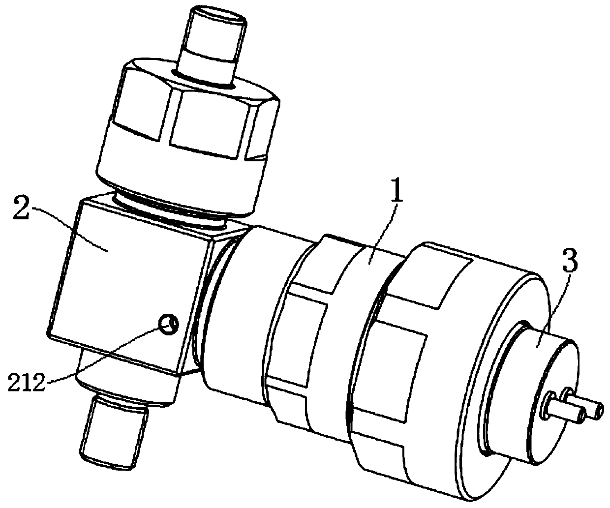
Figure 1 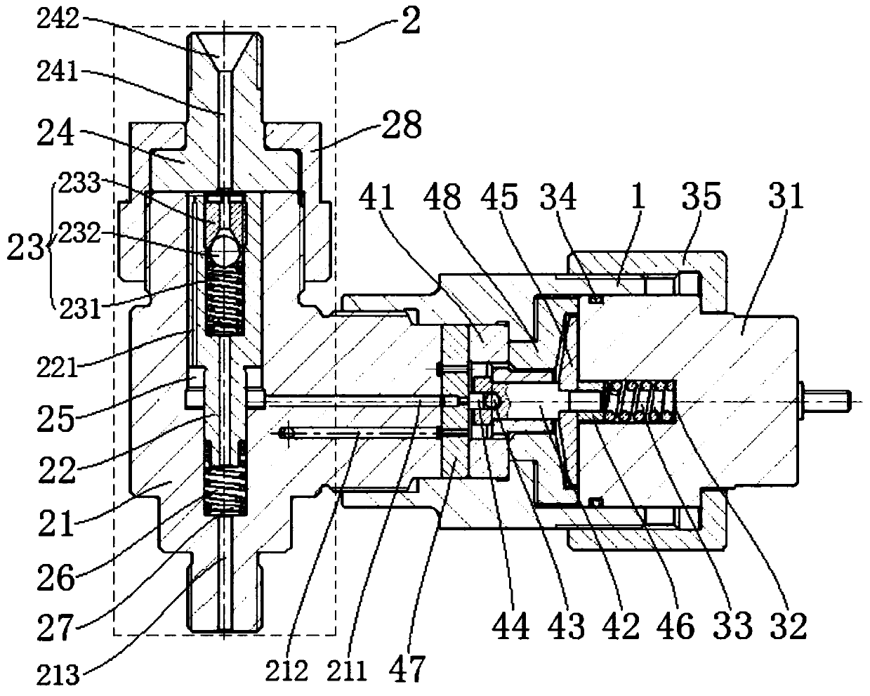
Figure 2 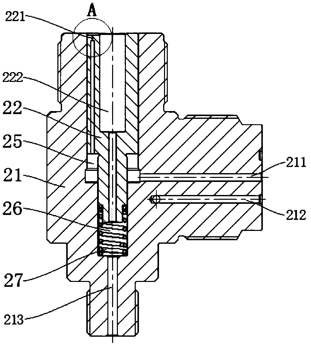
Figure 3
Abstract
Description
technical field
[0001] The invention relates to a diesel engine, in particular to a high-pressure fuel electronically controlled booster pump for a diesel engine. Background technique
[0002] The fuel injection system is an important part of the diesel engine, and the fuel injection pressure will directly affect the performance and emission of the diesel engine. With the increasingly stringent emission regulations and the demand for motion optimization in all working conditions, the shortcomings of the traditional mechanical fuel injection system and some shortcomings of the existing common rail system have gradually emerged. Compared with the traditional mechanical fuel injection system and the existing common rail system, the electronically controlled booster pump has the advantages of small modification scope of the diesel engine structure, low cost of modification, obvious improvement of the injection pressure of the system, and has great market promotion value. At pr...
Examples
Embodiment Construction
[0031] The present invention will be described in detail below in conjunction with the accompanying drawings and embodiments.
[0032] see Figure 1 to Figure 5 The shown high-pressure fuel electronically controlled booster pump for a diesel engine includes a housing 1, which is characterized in that it also includes a booster coupling 2 that is mated and connected with the left part of the housing 1, and that is connected with the housing 1. The solenoid valve assembly 3 that is matingly connected on the right, and the pressure relief assembly 4 tightly pressed in the housing 1 through the booster coupling 2 and the solenoid valve assembly 3; the booster coupling 2 includes the right end and the The booster pump body 21 matingly connected to the left part of the housing 1, the booster plunger 22 vertically arranged in the booster pump body 21 and matched with it, located in the booster pump body 21 and used to support The spring 27 of the booster plunger 22; a booster plunge...