
Optical lens
An optical lens, lens technology
Patent Information
- Authority / Receiving Office
- CN · China
- Patent Type
- Applications(China)
- Current Assignee / Owner
- Publication Date
- 2019-11-05
Smart Images
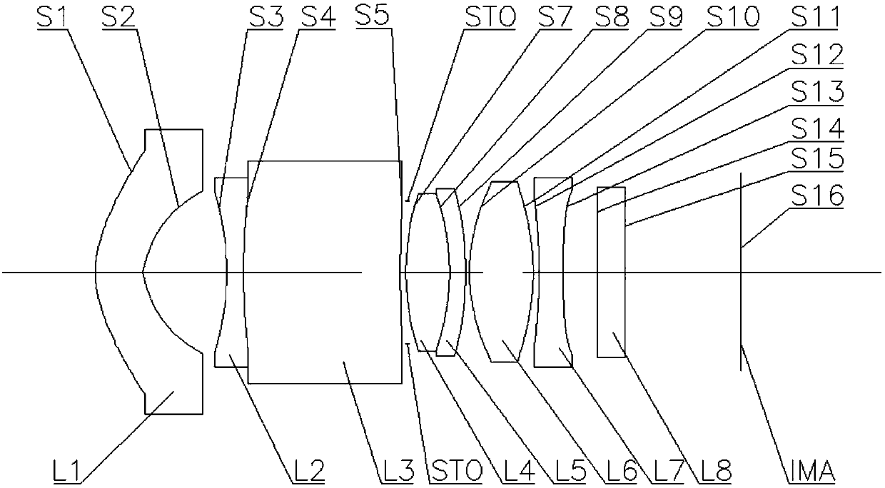
Figure 1 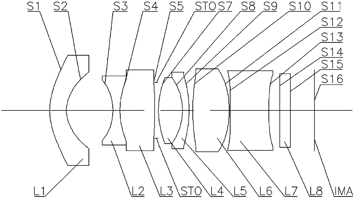
Figure 2 
Figure 3
Abstract
Description
Technical field
[0001] This application relates to the field of optics, specifically to optical lenses, and more specifically to optical lenses including seven lenses. Background technique
[0002] In recent years, with the development of active safety in the automotive industry, the requirements for automotive front-view lenses have continued to increase.
[0003] Large field of view, miniaturization, and high pixels are the prerequisites for this type of lens. At the same time, the requirements for the recognition of environmental objects are getting higher and higher. Specifically, the optical system is required to have a larger angular resolution. The angular resolution of the lens reflects the ability of the optical system to distinguish the smallest distance between two adjacent objects.
[0004] However, due to the large field of view, the focus range (DOF) of this type of optical lens is generally small, and the focal length is generally short. This makes it unable to meet...
Examples
Embodiment 1
[0064] The following reference figure 1 The optical lens according to Embodiment 1 of the present application is described. figure 1 A schematic structural diagram of an optical lens according to Embodiment 1 of the present application is shown.
[0065] Such as figure 1 As shown, the optical lens includes a first lens L1, a second lens L2, a third lens L3, a fourth lens L4, a fifth lens L5, a sixth lens L6, and a seventh lens in order from the object side to the imaging side along the optical axis. Lens L7.
[0066] The first lens L1 is a meniscus lens with a convex surface facing the object side with negative refractive power. The object side surface S1 is a convex surface, and the image side surface S2 is a concave surface. The second lens L2 is a biconcave lens with negative refractive power, and the object side surface S3 and the image side surface S4 are both concave. The third lens L3 is a meniscus lens with positive refractive power, the object side surface S4 is a convex ...
Embodiment 2
[0084] The following reference figure 2 The optical lens according to Embodiment 2 of the present application is described. figure 2 A schematic structural diagram of an optical lens according to Embodiment 2 of the present application is shown.
[0085] Such as figure 2 As shown, the optical lens includes a first lens L1, a second lens L2, a third lens L3, a fourth lens L4, a fifth lens L5, a sixth lens L6, and a seventh lens in order from the object side to the imaging side along the optical axis. Lens L7.
[0086] The first lens L1 is a meniscus lens with a convex surface facing the object side with negative refractive power. The object side surface S1 is a convex surface, and the image side surface S2 is a concave surface. The second lens L2 is a biconcave lens with negative refractive power, and the object side surface S3 and the image side surface S4 are both concave. The third lens L3 is a double convex lens with positive refractive power, and the object side surface S4 ...