
Tab, can lid, and method for manufacturing can lid
A technology of can lids and ring holes, which is applied in the field of manufacturing of pull rings, can lids and can lids, which can solve the problems of reduced opening performance and achieve the effect of simple structure
Patent Information
- Authority / Receiving Office
- CN · China
- Patent Type
- Applications(China)
- Current Assignee / Owner
- Publication Date
- 2020-12-04
Smart Images
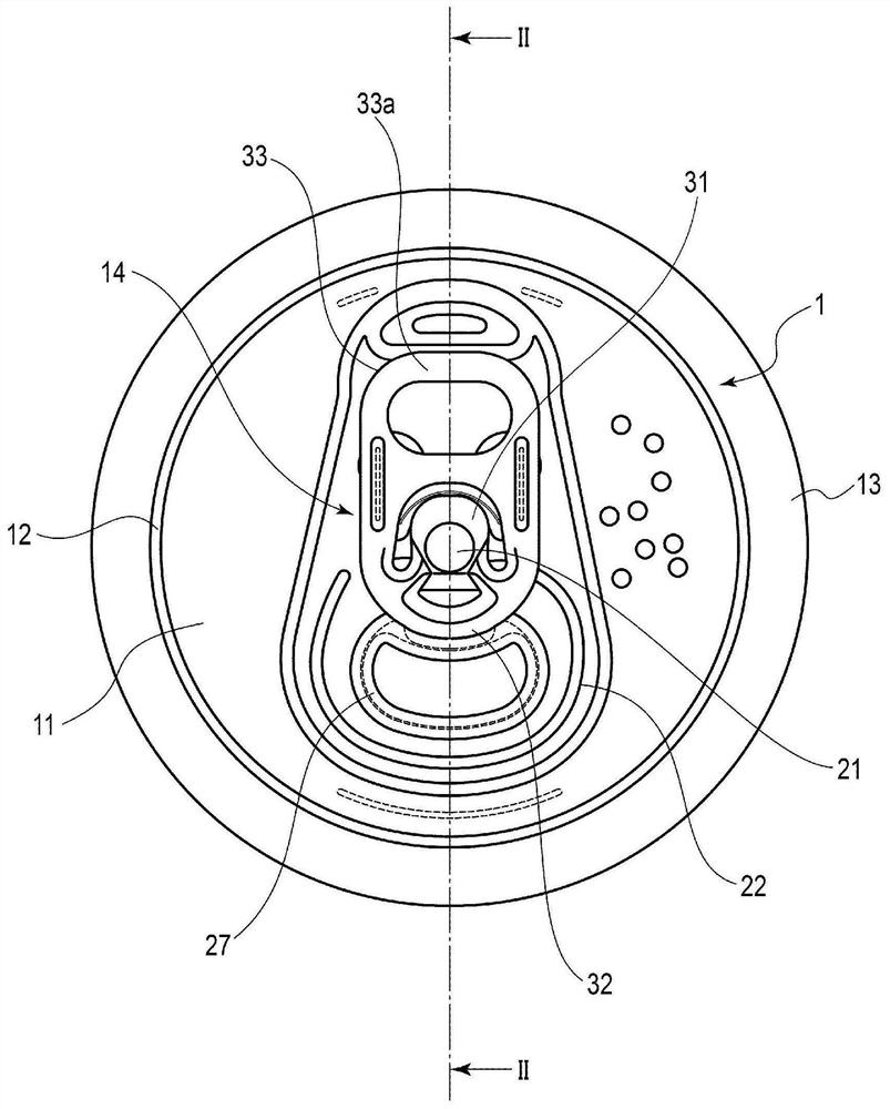
Figure 1 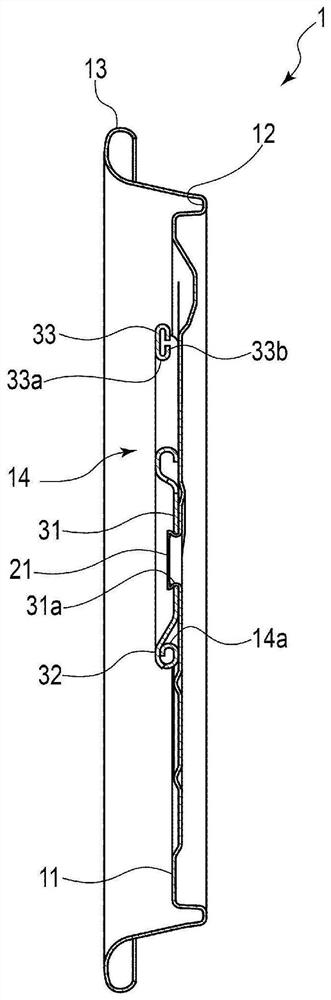
Figure 2 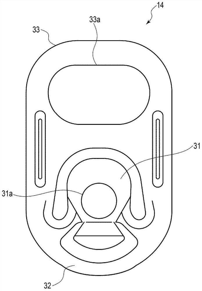
Figure 3
Abstract
Description
technical field
[0001] The invention relates to a pull ring used for a can container, a can lid and a method for manufacturing the can lid. Background technique
[0002] Conventionally, as can lids for can containers for beverages and food, stay-on-tab type can lids in which opening operations are performed by a pull ring are used. Such a can lid has a structure in which a part of the panel is broken along the score line by lifting the finger hook portion of the tab fixed to the panel by a rivet to open the panel.
[0003] Such a can lid fixes the tab to the panel portion by inserting a cylindrical rivet formed in the panel portion into a rivet hole formed in the tab and riveting the upper end of the rivet. Therefore, the tab is fixed to the panel portion so as to be rotatable in the circumferential direction around the rivet.
[0004] However, when the tab is rotated in the circumferential direction so that the center of the tab deviates from the line passing through the ...
Examples
Embodiment Construction
[0031] Below, use Figure 1 to Figure 9 The structure of the can end 1 having the tab 14 according to one embodiment of the present invention and the method of manufacturing the can end 1 will be described.
[0032] figure 1 It is a plan view showing the structure of the can lid 1 according to one embodiment of the present invention, figure 2 It is a sectional view showing the structure of the can lid 1 . image 3 as well as Figure 4 is a plan view showing the structure of the pull ring 14, image 3 Shown from the front side of the can lid 1, Figure 4 It is shown from the side of the panel portion 11 of the can lid 1 . Figure 5 It is a cross-sectional view showing a part of the tab 14 , that is, a structure of a material constituting the tab 14 . Figure 6 to Figure 8 It is an explanatory drawing which shows an example of each process of the manufacturing method of the can end 1, Figure 9 It is a flowchart showing an example of each step of the manufacturing method...