
Clothes airing device for smart home
A technology of smart home and drying device, which is applied to household clothes dryers, washing devices, household appliances, etc., can solve the problems of slow air flow, slow drying of clothes, and dry smell of clothes, etc., so as to improve uniformity and improve air-drying effect. , better effect
Patent Information
- Authority / Receiving Office
- CN · China
- Patent Type
- Applications(China)
- Current Assignee / Owner
- Publication Date
- 2021-06-11
- Estimated Expiration
- Not applicable · inactive patent
Smart Images
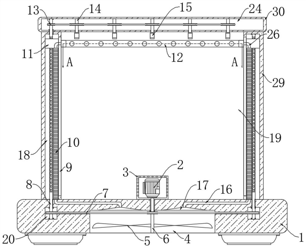
Figure 1 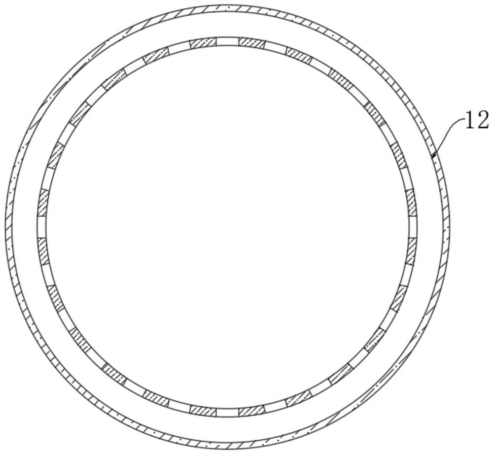
Figure 2 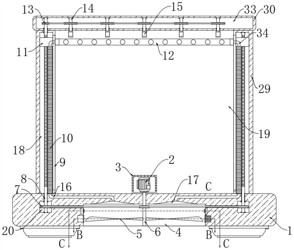
Figure 3
Abstract
Description
technical field
[0001] The invention relates to the technical field of smart home, in particular to a clothes drying device for smart home. Background technique
[0002] At present, the clothes hanger is the most important and commonly used support tool for drying clothes in people's life. With the continuous advancement of urbanization, urban buildings are getting higher and higher, and the places for people to dry clothes are getting smaller and smaller. Many residents can only Clothes racks are set on balcony and indoors to dry clothes, but the existing clothes have the following problems:
[0003] As more and more urban buildings are built, the rooms and balconies of some households cannot be exposed to sunlight. In this case, most people usually hang their clothes indoors to dry naturally after being dried by washing machines. The air flow rate is slow, so this drying method will make the clothes dry slowly in rainy days, and the clothes will have a dry smell during th...
Examples
Embodiment 1
[0025] refer to Figure 1-2 , a clothes drying device for smart home use, comprising a base 1, two support rods 29 are symmetrically installed on the upper end of the base 1, and a cross bar 30 is fixed on the upper ends of the two support rods 29, the base 1, the cross bar 30 and two The supporting rods 29 jointly form a drying space 19, the lower end of the base 1 is provided with a suction groove 4, and the base 1 is provided with two rotating cavities 20, and the two rotating cavities 20 are respectively located on the left and right sides of the suction groove 4, two Reciprocating chambers 18 are provided in the support rods 29, and transmission chambers 24 are provided in the crossbars 30;
[0026] Suction groove 4 is provided with suction mechanism, and suction mechanism comprises the housing 3 that is provided with the bottom in airing space 19, and housing 3 is provided with a plurality of cooling holes, is convenient to the heat dissipation of drive motor 2, and hous...
Embodiment 2
[0038] refer to Figure 3-4 The difference between this embodiment and Embodiment 1 is that two arc-shaped cavities 21 are arranged symmetrically on the left and right sides of the suction groove 4, and a moving block 22 is arranged in the two arc-shaped cavities 21, and the one on the left side The moving block 22 is magnetic, and one of the fan blades of the fan 5 is magnetic. The moving block 22 on the left side is attracted to the adjacent magnetic fan blade anisotropically. The inner wall is slidingly connected, and the rear side of the moving block 22 on the left side is elastically connected to the rear side inner wall of the corresponding arc cavity 21 through a return spring 23. The moving block 22 on the left side is fixedly connected to the side near the suction groove 4 The first friction plate 31, the inner wall of the suction groove 4 is provided with a heat conduction sheet 25, and the outer side of the heat conduction sheet 25 is provided with a second friction...