
Longitudinal-bending coupling double-foot linear plate type piezoelectric motor
A piezoelectric motor and coupling technology, applied in piezoelectric effect/electrostrictive or magnetostrictive motors, generators/motors, electrical components, etc., can solve the problems of coupled vibration, difficult assembly, large size, etc. Good output performance, easy miniaturization, high energy density effect
Patent Information
- Authority / Receiving Office
- CN · China
- Patent Type
- Applications(China)
- Current Assignee / Owner
- Publication Date
- 2022-05-06
Smart Images
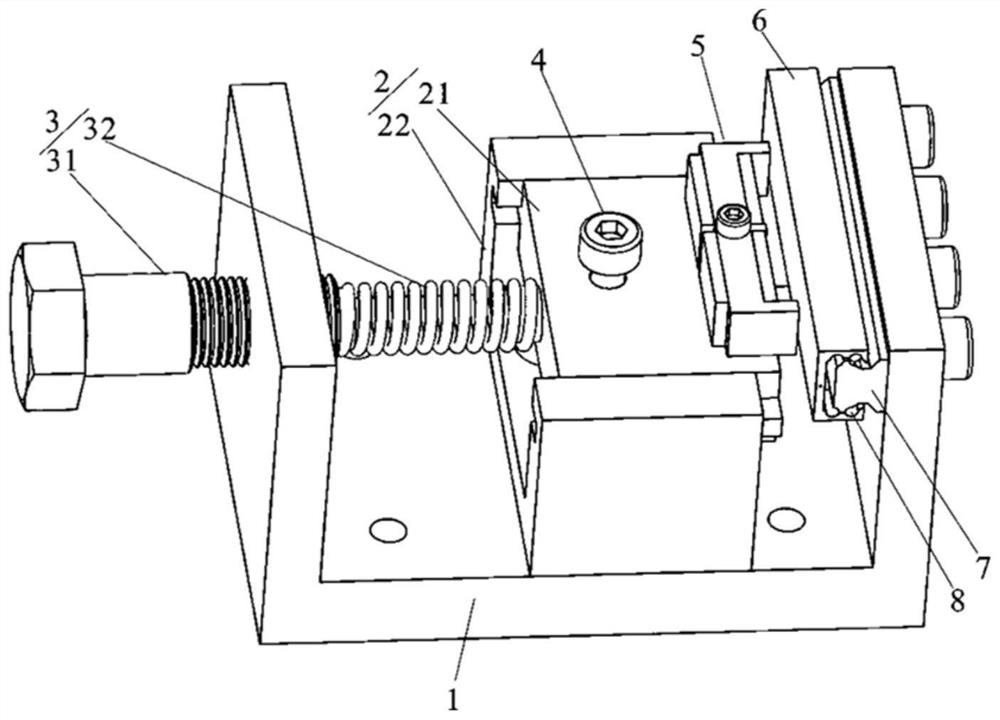
Figure 1 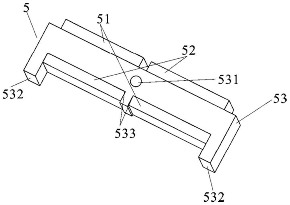
Figure 2 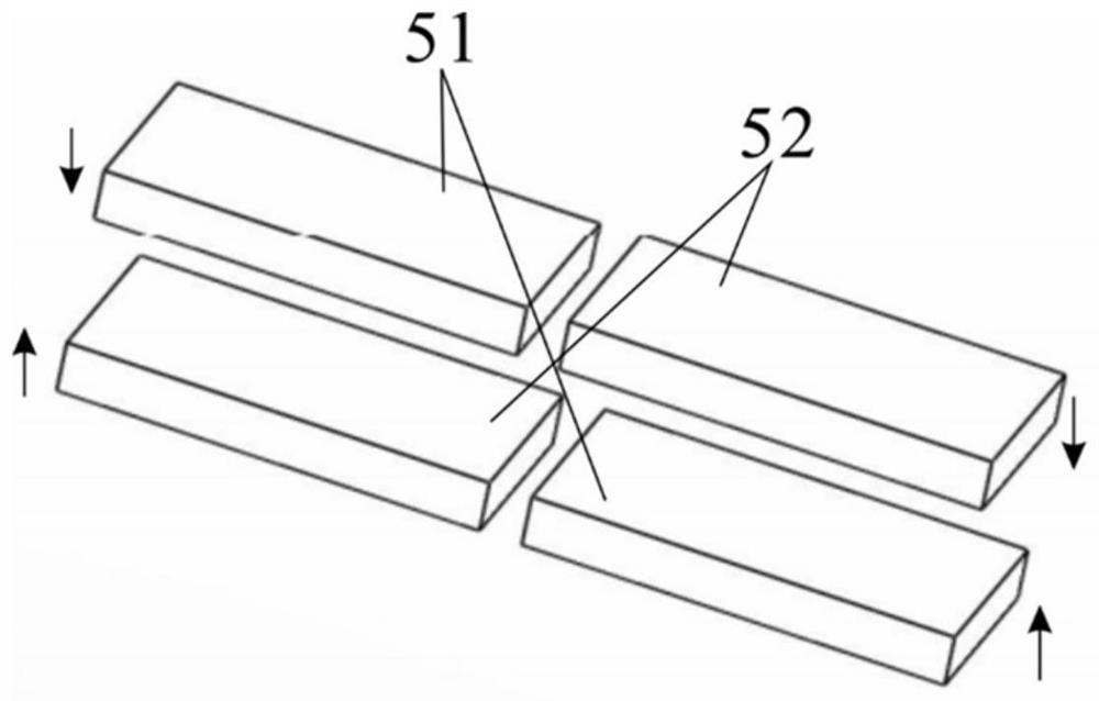
Figure 3
Abstract
Description
technical field
[0001] The invention relates to the technical field of piezoelectric motors, in particular to a longitudinal bending coupled biped linear plate piezoelectric motor. Background technique
[0002] The linear piezoelectric motor uses the inverse piezoelectric effect of piezoelectric ceramics to make the elastic body vibrate at a high frequency and slightly, and then converts electrical energy into mechanical energy through the frictional coupling between the stator and the mover to drive the mover to output linear motion. Linear motors have the characteristics of simple structure, direct drive of loads, high positioning accuracy and no electromagnetic interference. It has broad application prospects in micro-machines, precise positioning, and low-power drives.
[0003] Due to the limitation of the structure and working principle of the linear motor, the current linear motor still has problems such as complex structure, large volume, insufficient output performa...
Examples
Embodiment Construction
[0029] The following will clearly and completely describe the technical solutions in the embodiments of the present invention with reference to the drawings in the embodiments of the present invention. Obviously, the described embodiments are part of the embodiments of the present invention, not all of them. Based on the embodiments of the present invention, all other embodiments obtained by persons of ordinary skill in the art without making creative efforts shall fall within the protection scope of the present invention.
[0030] The following is attached Figure 1-6 The embodiment of the present invention is described in detail. A longitudinal bending coupled biped linear plate piezoelectric motor provided in this embodiment includes a stator 5, a mover slider 7, a base 1, a pre-pressure device 3, and a sliding mechanism 2. A guide rail 7 is fixed on the baffle on the right side of the base, and a ball 8 is arranged between the mover slider 6 and the guide rail 7 to reduce ...