
Garage door anti-picking lock
A garage door, anti-prying technology, applied in the field of garage doors, can solve the problem of not having anti-prying function and the like
Patent Information
- Authority / Receiving Office
- CN · China
- Patent Type
- Applications(China)
- Current Assignee / Owner
- Publication Date
- 2004-02-25
- Estimated Expiration
- Not applicable · inactive patent
Smart Images
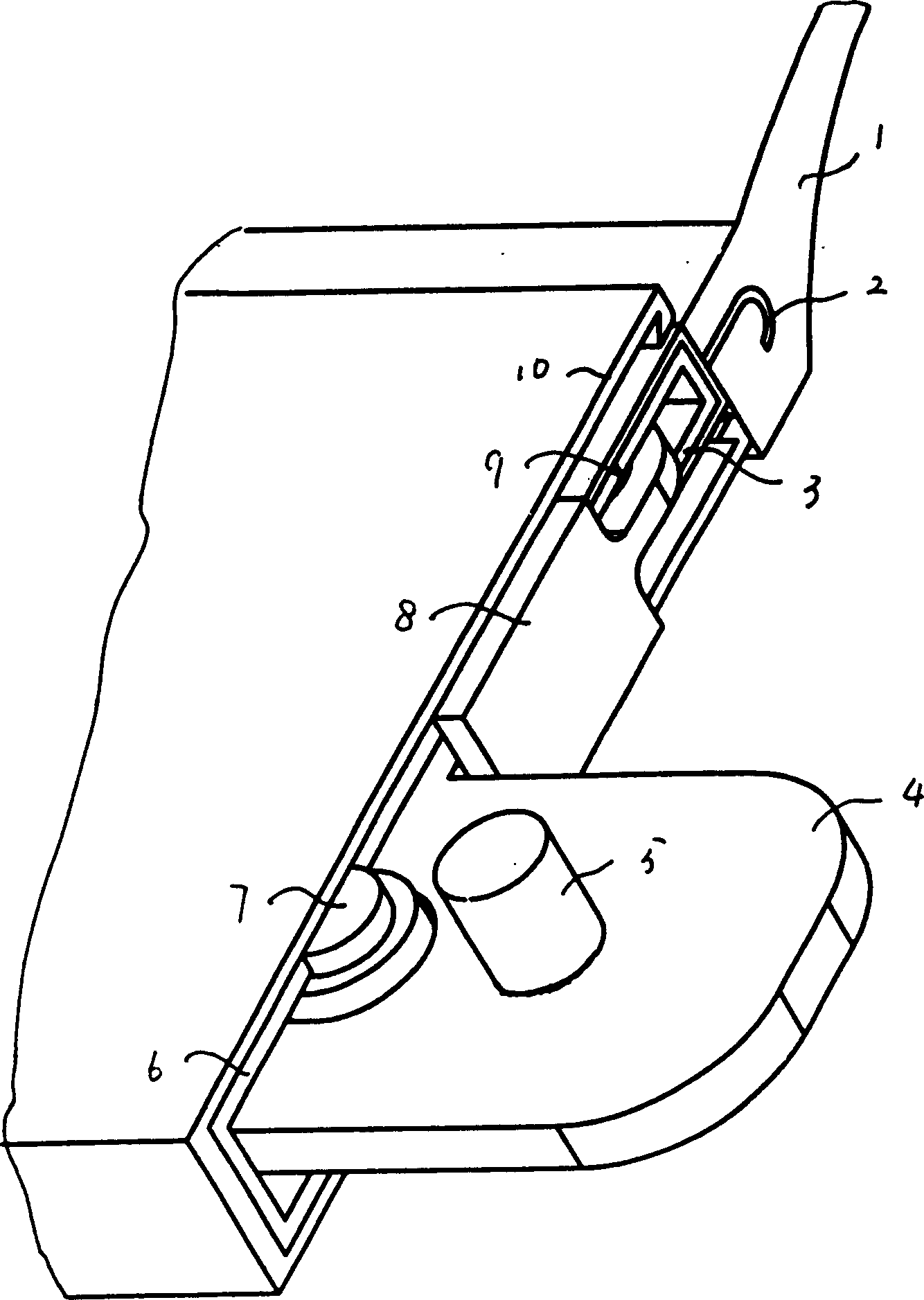
Figure 1 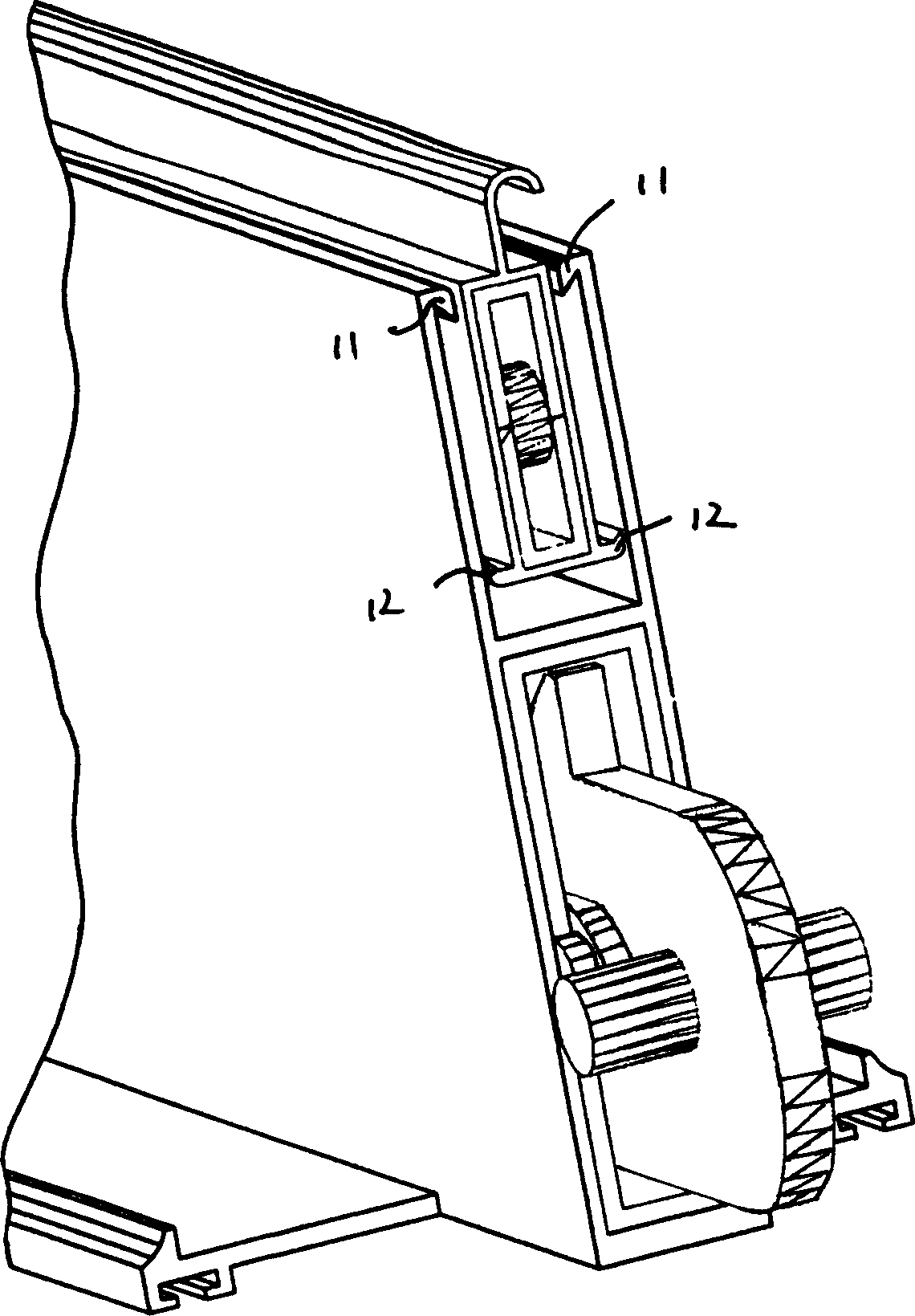
Figure 2 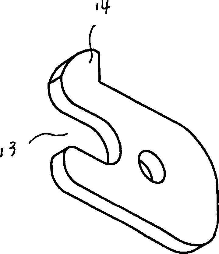
Figure 3
Abstract
Description
Technical field:
[0001] The invention relates to a garage door. In particular, it relates to an anti-pick lock for garage doors. Installed on the guide rails on both sides of the garage door panel and the bottom edge of the door panel. Background technique:
[0002] At present, the electric rolling shutter door commonly used in the market does not use an anti-prying mechanism between the guide rails on both sides and the bottom edge, and only relies on the dead weight of the door panel to lock the door panel. Therefore, it does not have anti-pry function. Invention content:
[0003] The object of the present invention is to overcome the above-mentioned disadvantages and provide a garage door tamper-resistant lock with tamper-proof function.
[0004] The purpose of the present invention is achieved in this way: a garage door anti-pick lock, including the upper bottom beam, the lower bottom beam, blocks, cams, camshafts and transverse shafts, the lower sides of the upper ...
Examples
Embodiment Construction
[0010] like Figure 1~2 , the present invention is a kind of anti-pick lock of garage door. It mainly consists of upper bottom beam 2, lower bottom beam 10, clamping block 8, cam 4, upper inner sleeve 3, lower inner sleeve 6, pin shaft 9, cam shaft 5 and fixed transverse shaft 7. The top of the upper bottom beam 2 is shaped like a hook, and the upper inner casing 3 is stuck in the inner cavity of the upper bottom beam 2, and the upper bottom beam 2 is hung on the door sheet 1 by the hook on its top. The two sides of the lower part of the upper bottom beam 2 extend outwards with outer oblique hooks 12, and the upper ends of the two sides of the lower bottom beam 10 extend inwards with inner oblique hooks 11. The upper bottom beam 2 is inserted in the middle of the upper part of the lower bottom beam 10, and the outer The oblique hook 12 is arranged below the inner oblique hook 11 of the lower bottom beam 10, and cooperates with the inner oblique hook 11 to enable the upper and...