
Intelligent safety box
A safe and intelligent technology, applied in the field of intelligent safes, can solve problems such as cracking, and achieve the effects of strong confidentiality, no risk of electric shock, and high safety
Patent Information
- Authority / Receiving Office
- CN · China
- Patent Type
- Patents(China)
- Current Assignee / Owner
- Publication Date
- 2011-11-30
Smart Images
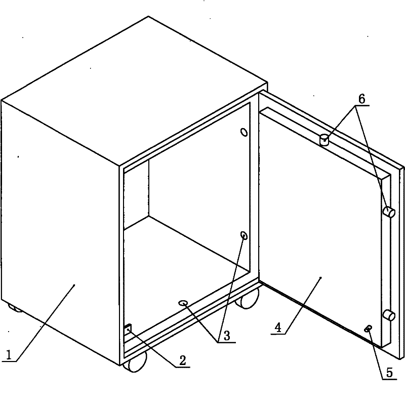
Figure 1 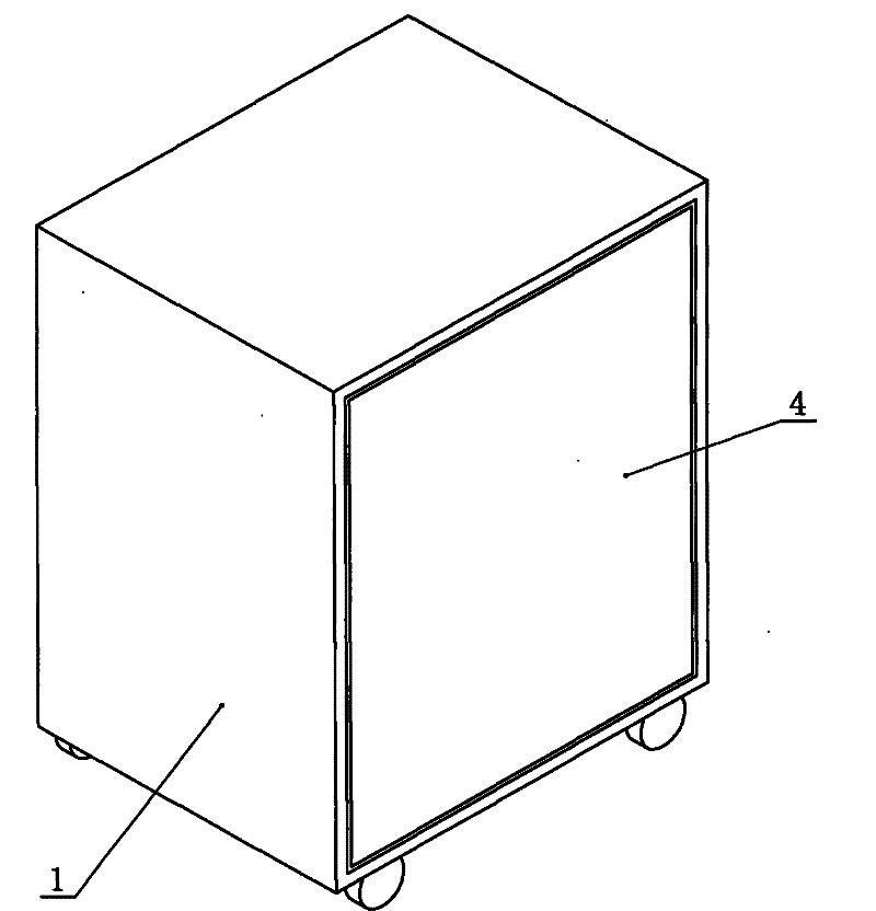
Figure 2 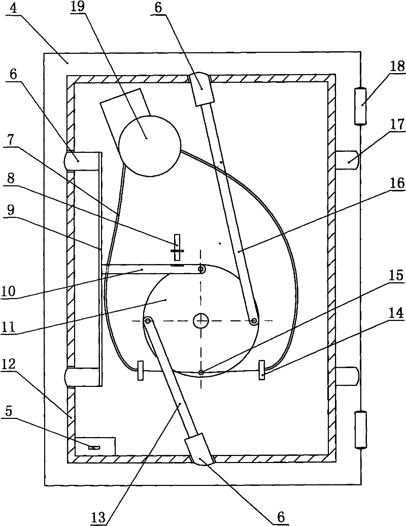
Figure 3
Abstract
Description
technical field
[0001] The invention relates to a safe, in particular to an intelligent safe with computer control and electromechanical integration. Background technique
[0002] my country updated the national standard GB10409-2001 on anti-theft safes in 2001. So far, there has been no major change in the appearance and technology of safes. So far, all safes on the market are mechanical locks, electronic combination locks, and fingerprint locks. As an unlocking lock, no matter how complicated its structure is, it is always possible to crack it, especially the seemingly complicated electronic combination lock and fingerprint lock. They all have an emergency unlocking device, that is to say, no matter what other devices in the safe How complicated, as long as the emergency device is opened, the safe can be opened. Contents of the invention
[0003] In order to avoid the above disadvantages, the object of the present invention is to provide an intelligent safe that does not ...
Examples
Embodiment Construction
[0022] The present invention will be further described below in conjunction with accompanying drawing and specific embodiment:
[0023] Intelligent safe of the present invention such as figure 1 , figure 2 , image 3 , Figure 4 As shown, it includes: cabinet body 1 and cabinet door 4, cabinet body 1 and cabinet door 4 are connected by hinge 18 (see image 3 ). Correspondingly have keyhole 3,21 on cabinet body 1 and cabinet door 4, DC motor tractor 19 and traction rotary disk 11 are housed in cabinet door 4 door bodies. One end of connecting rod 10,13,16 is respectively connected on the traction rotary disk 11, and the other end of connecting rod 10,13,16 is respectively connected with movable lock 6, or is connected with movable lock 6 by connecting rod 9.
[0024] DC motor tractor 19 can be selected for use known automobile window lifter to replace.
[0025] Movable lock 6 is positioned in the lockhole 21 on the cabinet door 4, and expands and contracts along the lock...