
Knob switch device
Patent Information
- Authority / Receiving Office
- US · United States
- Current Assignee / Owner
- Publication Date
- 2019-12-10
Smart Images
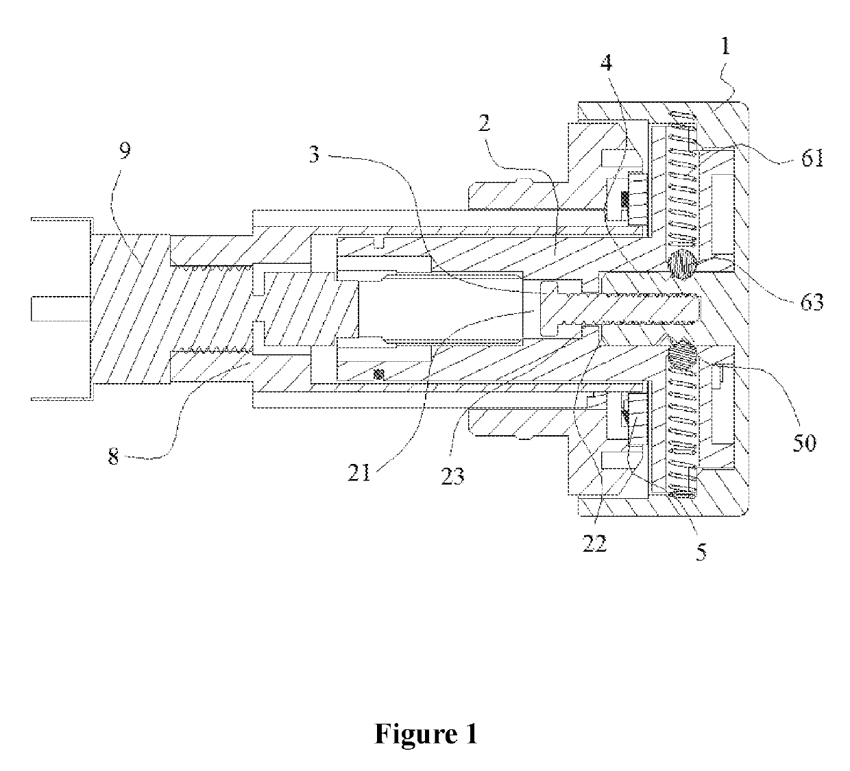
Figure 1 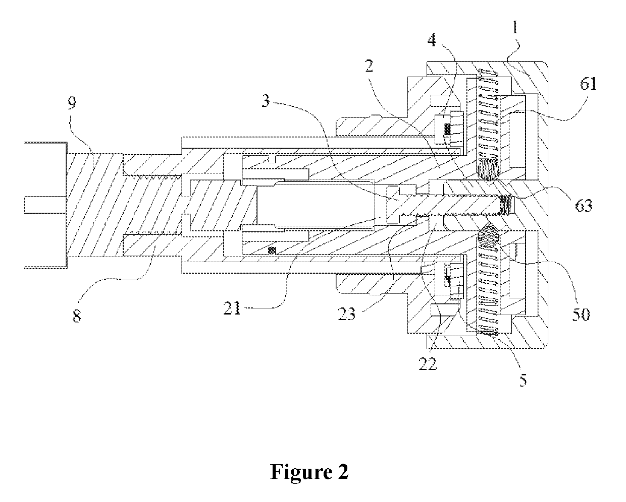
Figure 2 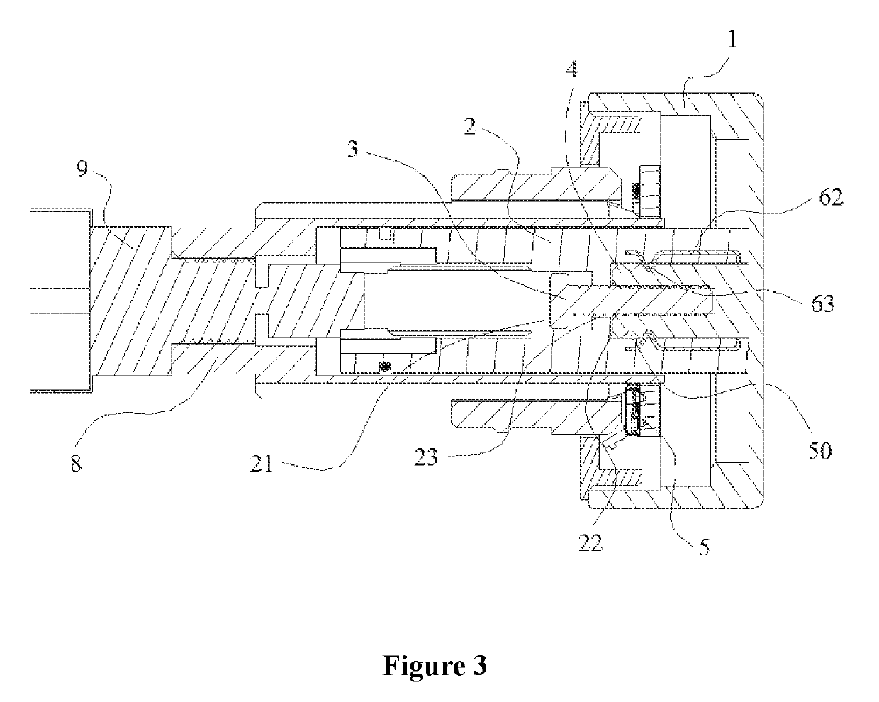
Figure 3
Abstract
Description
CROSS-REFERENCE TO RELATED APPLICATION
[0001] The present application is a national phase entry under 35 U.S.C. § 371 of International Application No. PCT / CN2016 / 102639, filed Oct. 20, 2016, entitled “KNOB SWITCH DEVICE,” which designates the United States of America, which claims priority to Chinese Patent Application No. 201520818161.1, filed Oct. 21, 2015 with the State Intellectual Property Office of People's Republic of China, both of which are incorporated herein by reference in their entireties.FIELD
[0002] The present disclosure relates to the technical field of intelligent sanitary devices, relates to a contact-type switch, and in particular to a knob switch device for an intelligent pedestal pan.BACKGROUND
[0003] With the development of science and technology and the improvement of a living standard of people, an intelligent pedestal pan gets more and more popular because of its simple manipulation, comfortable experience and rich intelligent functions. In addition to basic func...
Examples
first embodiment
[0038]In the present disclosure, a trigger mechanism includes a clamping unit and a clamping slot 50 (in this embodiment, two of the clamping slots 50 are arranged at intervals, and the clamping slots 50 are connected to the outside of an extension part 4 of a knob 1 to form an end-to-end circular orbit) in cooperation with each other. As shown in FIG. 1 and FIG. 2, the clamping unit is a kind of a flexible structure, which includes an elastic element (a spring 61 in this embodiment) and a clamping element 63 arranged at an end of the elastic element (the spring 61 in this embodiment). One end of the spring 61 is fixed on an inner wall of the knob 1, and the other end of the spring 61 extends toward the extension part 4 of the knob 1. A length of the spring 61 can meet the requirement of getting into and signing out from the clamping slot 50 for the clamping element 63, and elasticity of the spring 61 should ensure a certain intensity, namely, the clamping element 63 will not sign o...
second embodiment
[0042]In the present disclosure, a trigger mechanism includes a clamping unit and a clamping slot 50 (in this embodiment, two of the clamping slots 50 are arranged at intervals, and the clamping slots 50 are connected to the outside of an extension part 4 of a knob 1 to form an end-to-end circular orbit) in cooperation with each other. As shown in FIG. 3 and FIG. 4, the clamping unit is a kind of a flexible structure, which includes an elastic element (a spring piece 62 in this embodiment) and a clamping element 63 arranged at the end of the elastic element (the spring piece 62 in this embodiment). One end of the spring piece 62 is fixed on the outside of the extension part 4 of the knob 1, and the other end of the spring piece 62 extends in an axial direction of the extension part 4 of the knob 1. The length of the spring piece 62 can meet the requirement of getting into and signing out from the clamping slot 50 for the clamping element 63, and the elastic force of the spring piece...
third embodiment
[0046]In the present disclosure, a trigger mechanism includes a clamping unit and a clamping slot 50 (in this embodiment, the clamping slot 50 is connected to the outside of an extension part 4 of a knob 1 to form an end-to-end circular orbit) in cooperation with each other. As shown in FIG. 5 and FIG. 6, the clamping unit is a kind of a flexible structure, which includes an elastic element (a spring piece 62 in this embodiment) and a clamping element 63 arranged at the end of the elastic element (the spring piece 62 in this embodiment). One end of the spring piece 62 is fixed on the outside of the extension part 4 of the knob 1, and the other end of the spring piece 62 extends in an axial direction of the extension part 4 of the knob 1. The length of the spring piece 62 can meet the requirement of getting into and signing out from the clamping slot 50 for the clamping element 63, and the elastic force of the spring piece 62 should ensure a certain intensity, namely, the clamping el...