
Inkjet printer
a technology of inkjet printers and recording heads, applied in printing, other printing apparatuses, etc., can solve the problem of first ink discharged from recording heads not being cured
Patent Information
- Authority / Receiving Office
- US · United States
- Patent Type
- Patents(United States)
- Current Assignee / Owner
- Publication Date
- 2022-10-11
Smart Images
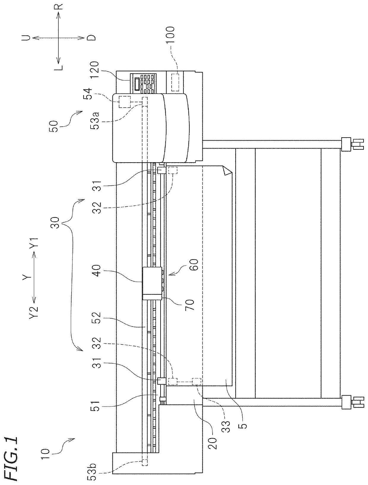
Figure 1 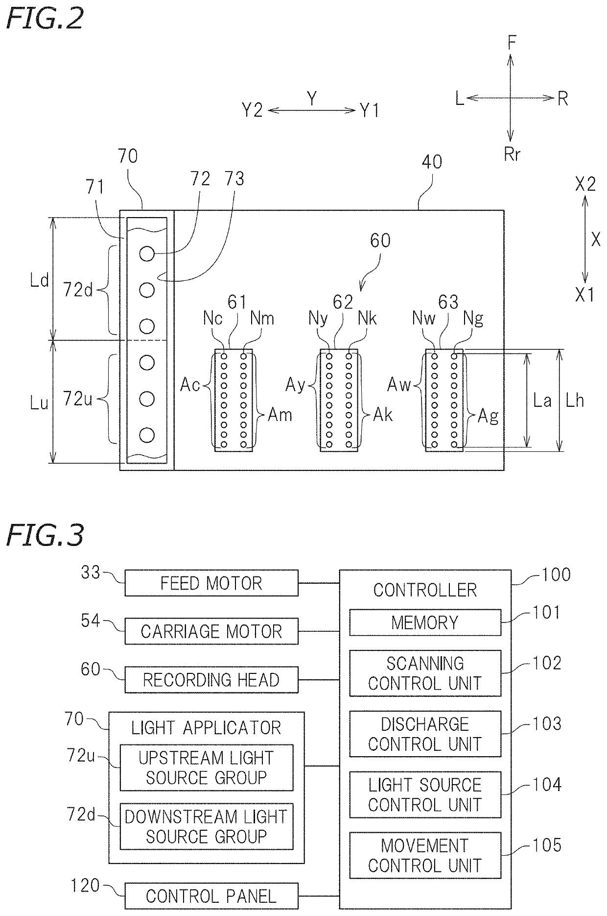
Figure 2 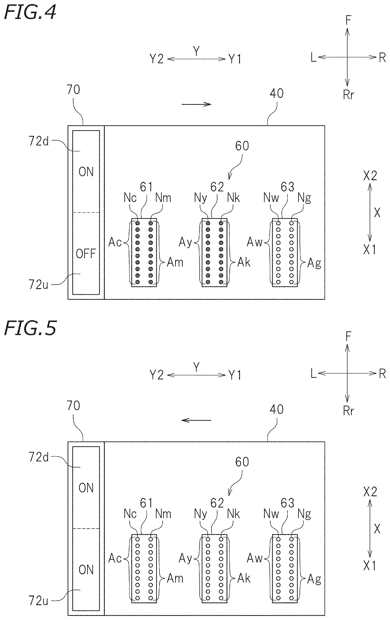
Figure 3
Abstract
Description
CROSS REFERENCE TO RELATED APPLICATIONS
[0001] This application claims the benefit of priority to Japanese Patent Application No. 2020-105172 filed on Jun. 18, 2020. The entire contents of this application are hereby incorporated herein by reference.BACKGROUND OF THE INVENTION1. Field of the Invention
[0002] The present invention relates to inkjet printers.2. Description of the Related Art
[0003] Inkjet printers known in the related art discharge photo-curable ink onto recording media and apply light to the photo-curable ink discharged, thus forming images on the recording media. For such inkjet printers, various techniques have been developed regarding positional relationships between light applicators and recording heads to discharge photo-curable ink and temporal relationships between ink discharge timings and light application timings.
[0004] JP 2009-202418 A, for example, discloses an inkjet printer including: a support that supports a recording medium; a carriage that moves in a right...
Examples
first preferred embodiment
[0028]FIG. 1 is a front view of a large format inkjet printer (hereinafter referred to as a “printer”) 10 according to a first preferred embodiment of the present invention. The printer 10 moves a recording medium 5 in a roll form in a front-rear direction and discharges ink from a recording head 60 mounted on a carriage 40 that moves in a right-left direction. The printer thus prints an image on the recording medium 5. In the following description, the right-left direction in which the carriage 40 moves may also be referred to as a “scanning direction Y”, and the front-rear direction in which the recording medium 5 moves may also be referred to as a “conveyance direction X” (see FIG. 2).
[0029]The recording medium 5 is an object on which an image is to be printed. The recording medium 5 is not limited to any particular type of recording medium. Examples of the recording medium 5 may include paper, such as plain paper and inkjet printing paper, and transparent sheets, such as a resin...
second preferred embodiment
[0075]An inkjet printer according to a second preferred embodiment of the present invention performs bidirectional printing. Accordingly, the inkjet printer includes additional components, and some of control operations performed by the inkjet printer are changed. Other than these differences, the second preferred embodiment is similar to the first preferred embodiment. In the following description of the second preferred embodiment, components having the same functions as those of the first preferred embodiment will be identified by the same reference signs. Description of features of the second preferred embodiment overlapping those of the first preferred embodiment will be omitted or simplified.
[0076]FIG. 8 is a partially cut-away plan view schematically illustrating the arrangement of components on the lower surface of a carriage 40 according to the second preferred embodiment. As illustrated in FIG. 8, a printer 10 according to the present preferred embodiment includes a first ...