
Pulse duty cycle automatic correction device and method thereof
Patent Information
- Authority / Receiving Office
- US · United States
- Current Assignee / Owner
- Publication Date
- 2005-03-31
Smart Images
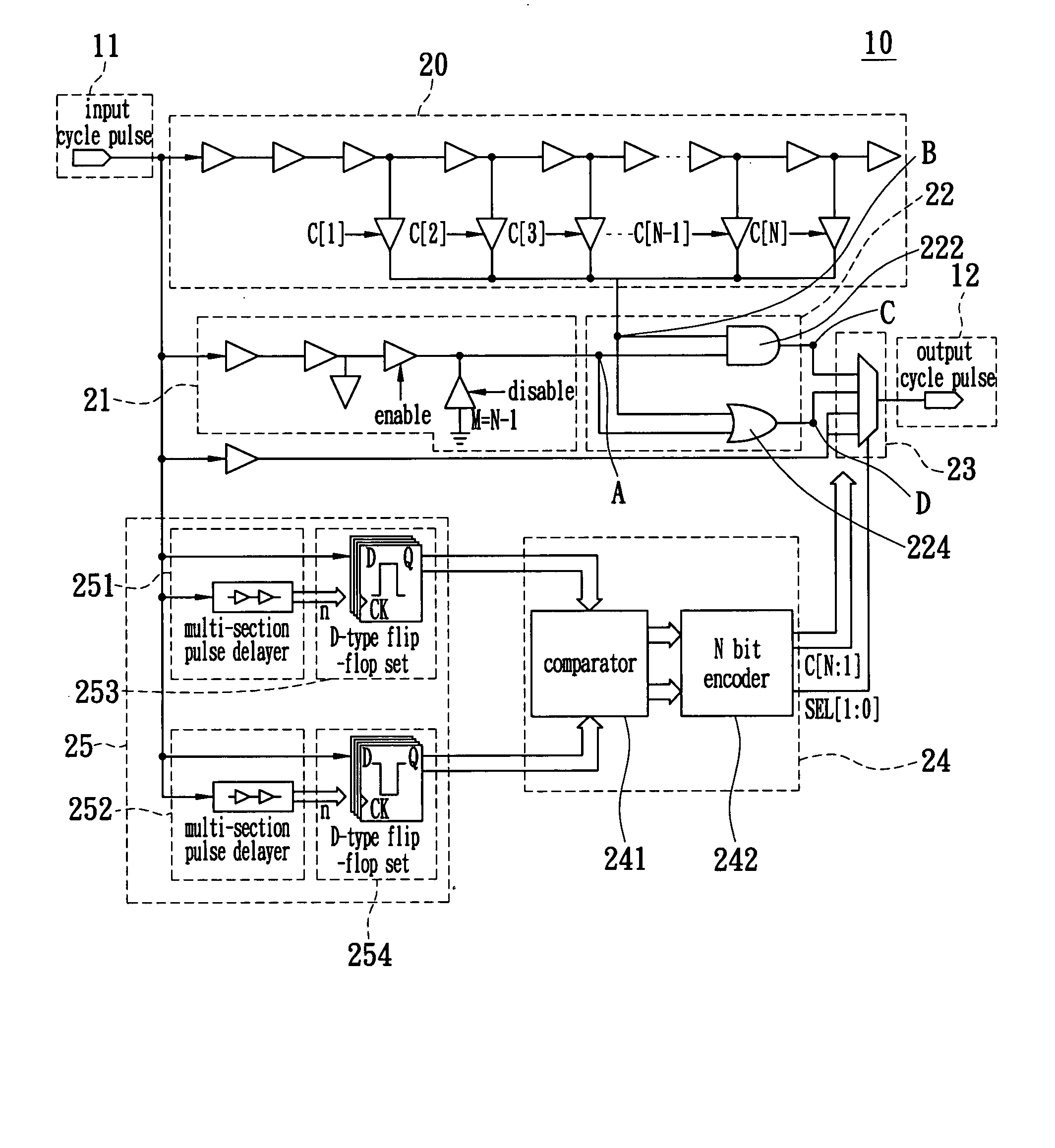
Figure 1 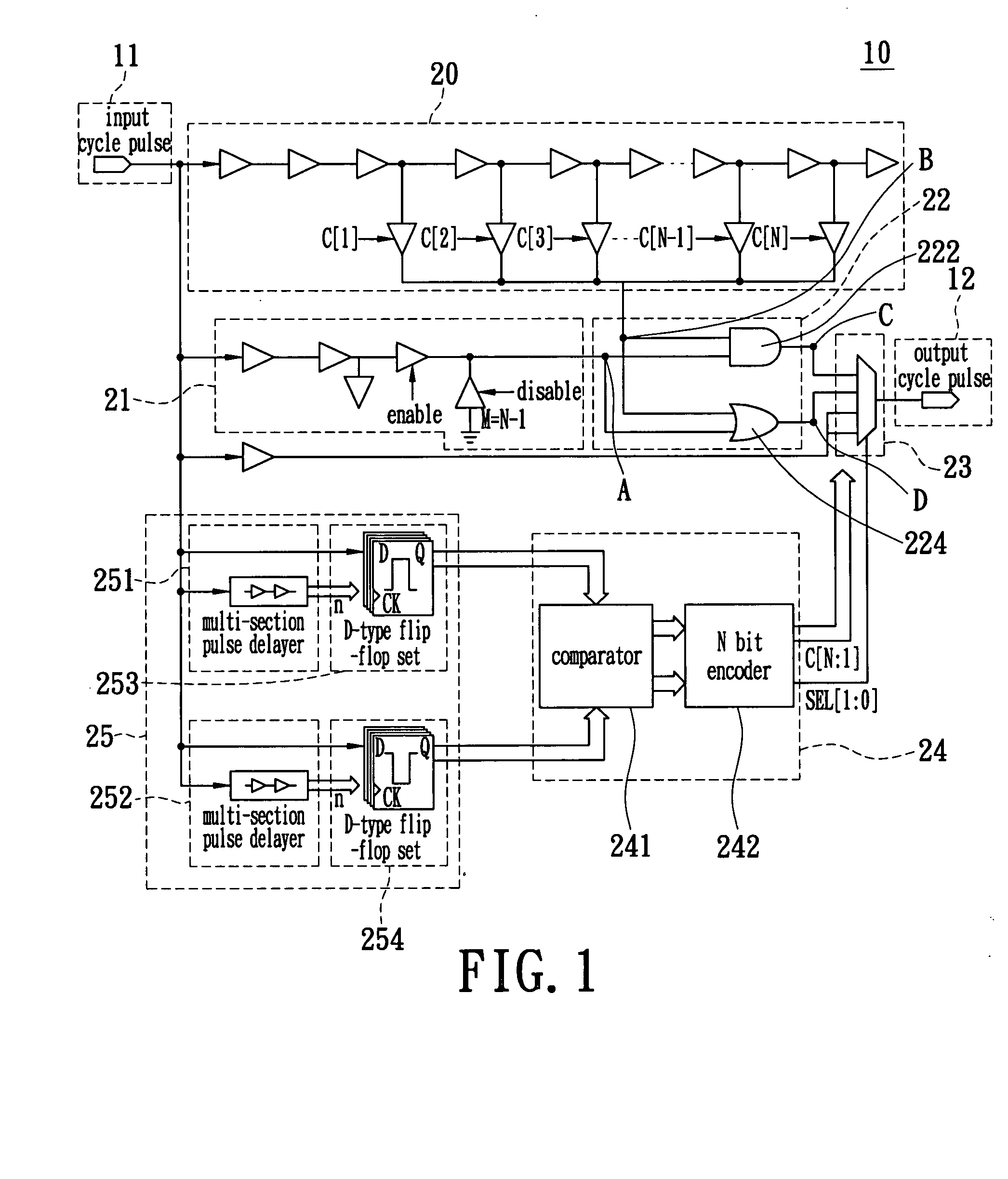
Figure 2 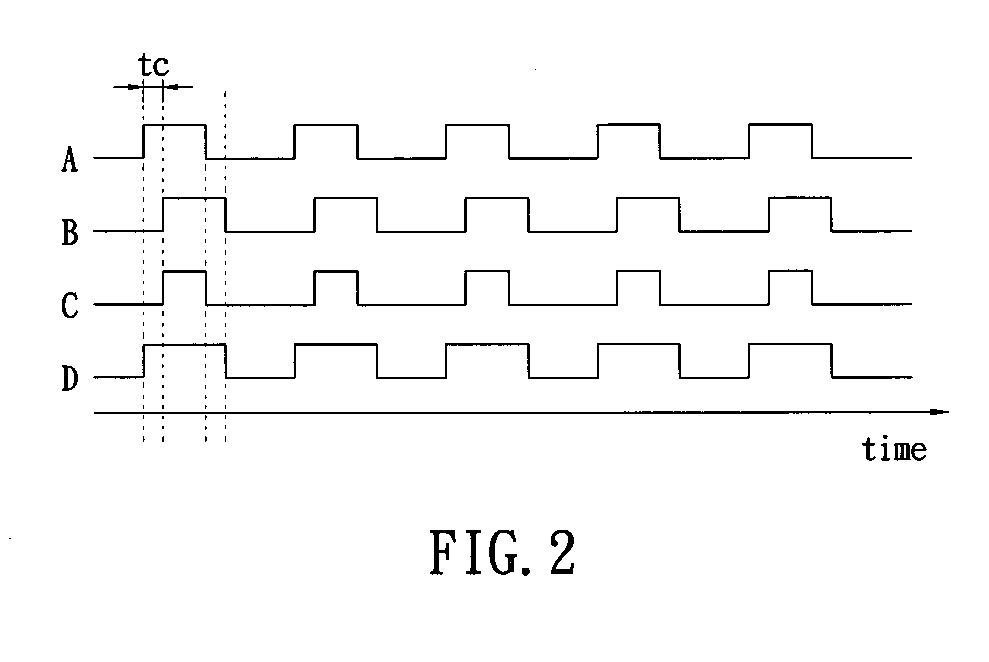
Figure 3
Abstract
Description
BACKGROUND OF THE INVENTION
[0001] 1. Field of the Invention
[0002] The present invention relates to a pulse duty cycle automatic correction device and a method thereof, and more particularly, to an automatic correction device and a method thereof for stabilizing the pulse duty cycle of the cycle pulse signal to be 50%.
[0003] 2. Description of the Prior Art
[0004] As electronic technology advances, various electronic devices make daily life more convenient and enjoyable, and enrich the people's life. People are more dependent on electronic devices, and it is thus important to improve the stability of the electronic devices. Generally, when transmitting and processing electronic data, a system must be operated in coordination with the specific pulses so as to correctly analyze the serial format in the data content and process the data in harmony. Therefore, when designing the output / input circuits of the electrical circuits, the stability of the work pulse duty cycle is very importa...
Examples
Embodiment Construction
[0016] Reference is made to FIG. 1. FIG. 1 is a block diagram of a pulse duty cycle automatic correction device 10 according to the present invention. The pulse duty cycle automatic correction device 10 will generate a proportional cycle pulse according to the input cycle pulse 11, namely, an output cycle pulse 12. The pulse duty cycle automatic correction device 10 comprises a delay circuit 20, a compensation circuit 21, a logic circuit 22, a multiplexer 23, a comparator encoder 24, and a pulse width detector 25.
[0017] The pulse width detector 25 is composed of multi-section pulse delayers 251, 252 and D-type flip-flop sets 253, 254. The multi-section pulse delayers 251, 252 are separately connected to the D-type flip-flop sets 253, 254, and each of the D-type flip-flop sets 253, 254 comprises a plurality of D-type flip-flops. The pulse width detector 25 is used for receiving the input cycle pulse 11 and separately detecting the high level pulse width (DH) and the low level pulse ...