
Enhanced permanent magnet electromagnetic actuator for an electronic valve actuation system of an engine
Patent Information
- Authority / Receiving Office
- US · United States
- Current Assignee / Owner
- Publication Date
- 2005-12-22
- Estimated Expiration
- Not applicable · inactive patent
Smart Images
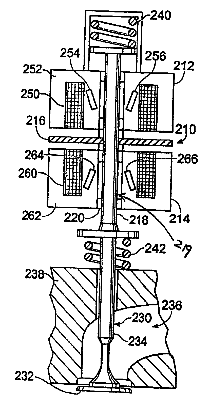
Figure 1 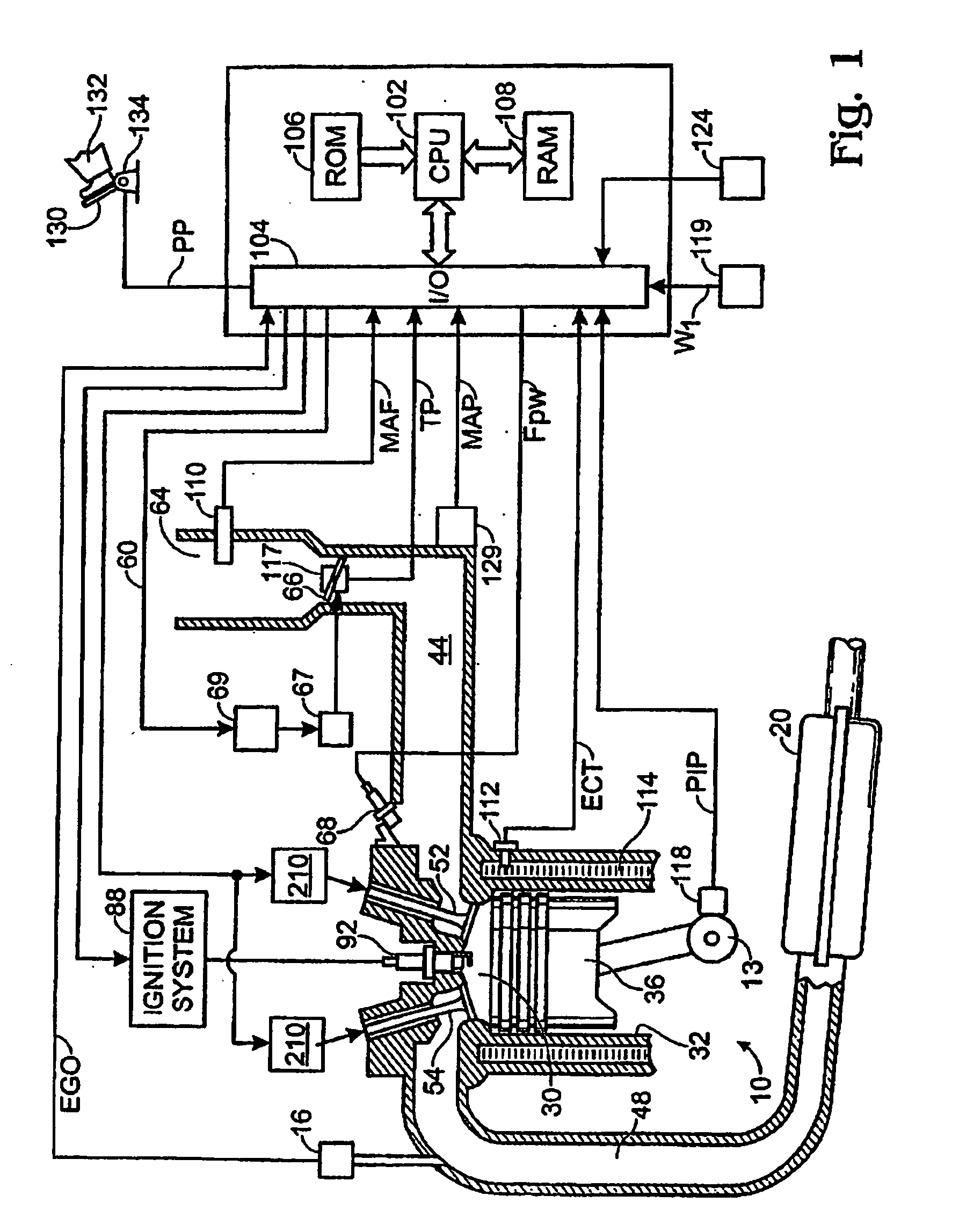
Figure 2 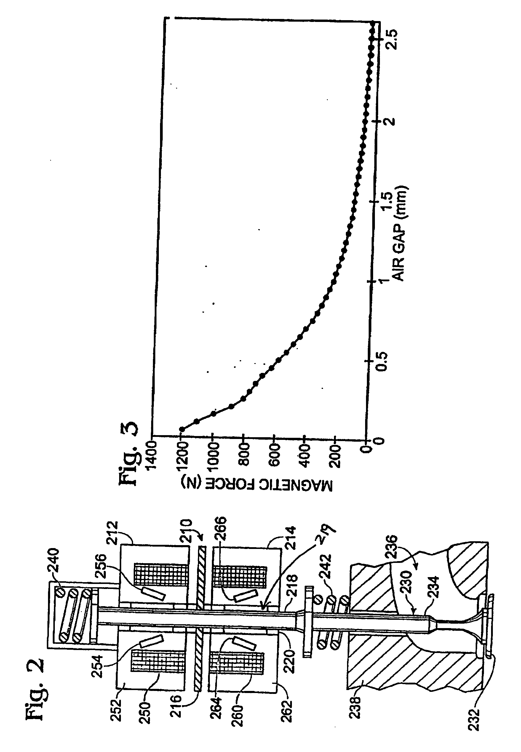
Figure 3
Abstract
Description
[0001] The present application is a continuation-in-part of, and claims priority to, U.S. patent application Ser. No. 10 / 873,711, filed Jun. 21, 2004, titled “enhanced PERMANENT MAGNET ELECTROMAGNETIC ACTUATOR FOR AN ELECTRONIC VALVE ACTUATION SYSTEM OF AN ENGINE” and having the same assignee as the present application, the entire contents of which are hereby incorporated by reference.FIELD
[0002] The field of the disclosure relates to electromechanical actuators coupled to cylinder valves of an internal combustion engine, and more particularly to a dual coil valve actuator. BACKGROUND AND SUMMARY
[0003] Electromechanical valve actuators for actuating cylinder valves of an engine have several system characteristics to overcome. First, valve landing during opening and closing of the valve can create noise and wear. Therefore, valve landing control is desired to reduce contact forces and thereby decrease wear and noise. However, in some prior art actuators, the rate of change of actua...
Examples
example a
[0113] Example A shows recess 3870 at the outer edge of the side poles, which is similar to recess 3690 of FIG. 36. Example B shows recess 3872 at the interior edge of the side poles. Example C shows a combination of recesses 3872 and recess 3874 on the exterior edges of the center pole, while Example D shows only recess 3874 on the edges of the center pole. Example E shows recess 3876 in the center region on the armature end of the center pole, similar to recess 3680. Example F shows multiple recesses 3876 (three) evenly spaces along the armature end edge of the center pole. Example G shows multiple recesses 3876 (three), one placed in the center region on the armature end edge of each of the two side poles and the center pole. Example H shows multiple recesses 3878 in the shape of a rectangular notch at each corner of the armature edge of the poles and the coil cavity. Example I shows a half-circle shaped recess 3880 in the center region of the armature edge of the center pole. Re...