

Electro-optical device and electronic apparatus
a technology of electro-optical devices and electronic devices, applied in the direction of lighting and heating devices, electric apparatus casings/cabinets/drawers, instruments, etc., can solve the problems of panel flying out, increase the number of parts and steps, and hinder the display of electro-optical devices. , the effect of preventing the adhesion base from slipping
Patent Information
- Authority / Receiving Office
- US · United States
- Patent Type
- Applications(United States)
- Current Assignee / Owner
- Publication Date
- 2005-12-29
Smart Images
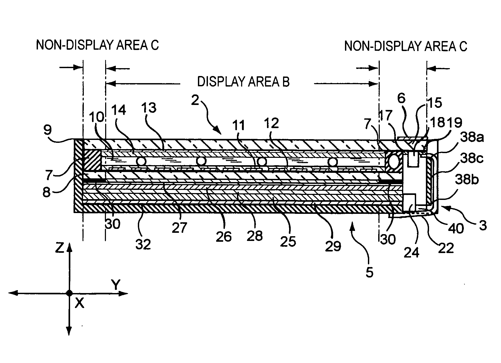
Figure 1 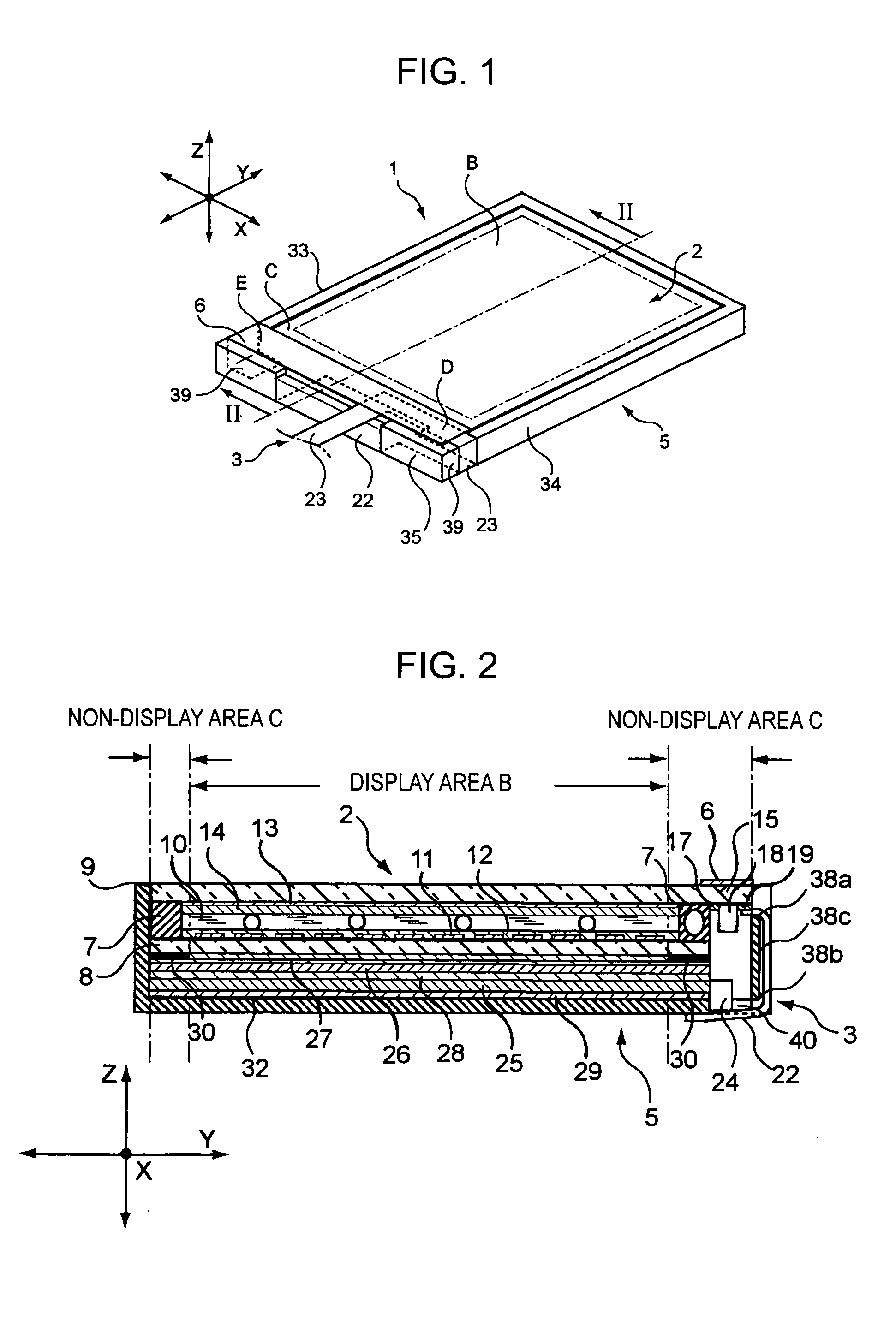
Figure 2 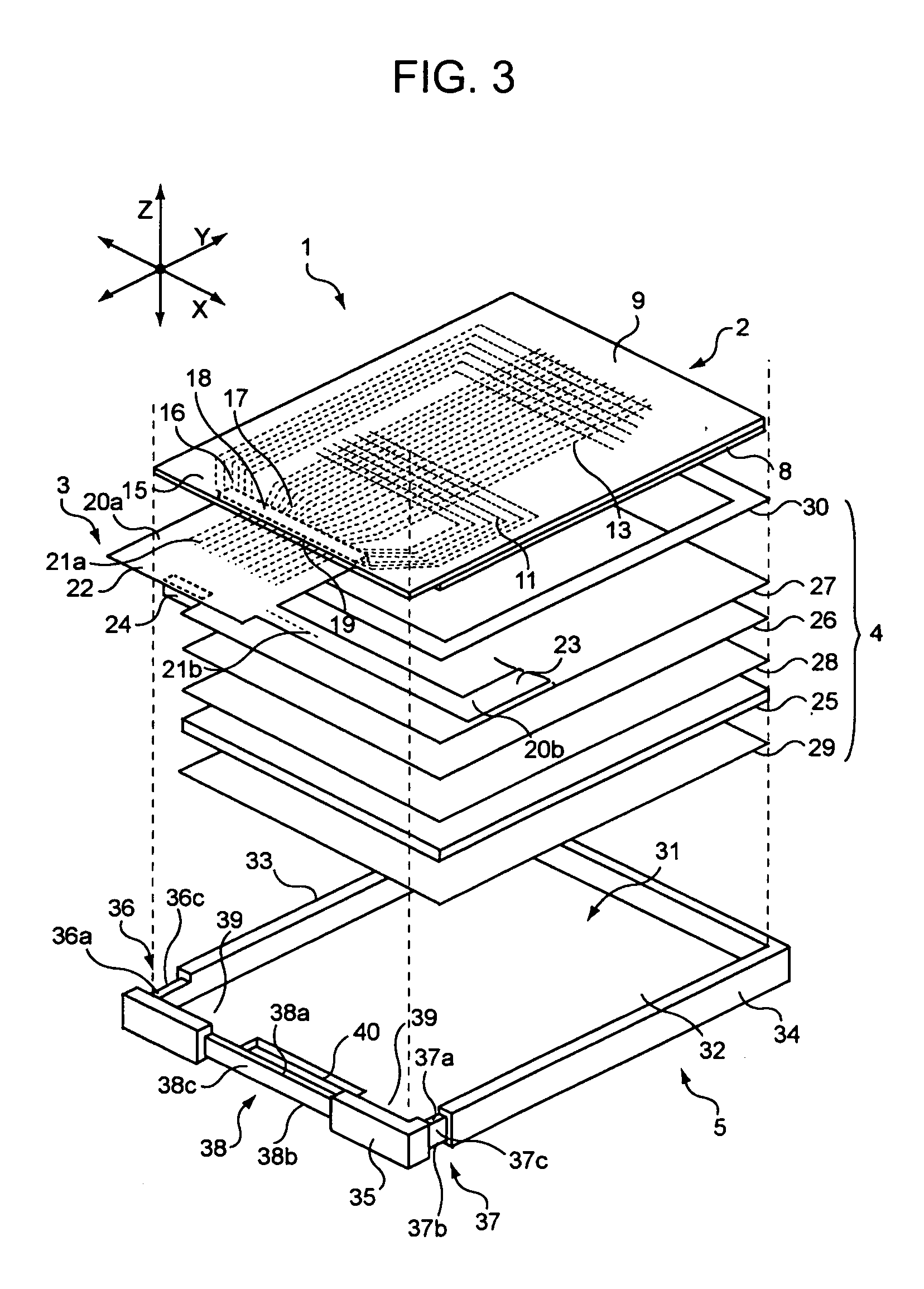
Figure 3
Abstract
Description
BACKGROUND OF THE INVENTION
[0001] 1. Technical Field
[0002] The present invention relates to an electro-optical device used in, for example, a personal computer or a cellular phone, and to an electronic apparatus using the electro-optical device.
[0003] 2. Related Art
[0004] Hitherto, an electro-optical device, such as a liquid crystal device, serving as a display device, of an electronic apparatus, such as a personal computer or a cellular phone, has been widely used.
[0005] There is a demand for personal computers, cellular phones, etc., to be smaller and lighter and to have a higher resistance to external shock applied when carrying such apparatuses. For the purposes of size reduction and increasing shock resistance, for example, a method which provides a shock-absorbing material having an adhesion portion for being adhered to a liquid crystal panel has been proposed (see, for example, Japanese Unexamined Patent Application Publication No. 2003-308023 (paragraphs 0009 to 0011, a...
Examples
first embodiment
[0041]FIG. 1 is a schematic perspective view of a liquid crystal device according to a first embodiment of the invention. FIG. 2 is a sectional view taken along line II-II shown in FIG. 1 (a liquid crystal driving IC and a light source are not shown in cross section). FIG. 3 is a schematic exploded perspective view of the liquid crystal device.
Structure of Liquid Crystal Device
[0042] As shown in, for example, FIGS. 1 to 3, a liquid crystal device 1 comprises, for example, a liquid crystal panel 2 serving as an electro-optical panel, a flexible board 3 serving as a flexible circuit board electrically connected to the liquid crystal panel 2, an illuminator 4 for illuminating the liquid crystal panel 2 with light, a frame 5 holding the liquid crystal panel 2 and the illuminator 4, and a light-shielding member 6 for intercepting light. Here, supplemental mechanisms (not shown) other than the frame 5 are provided in the liquid crystal device 1 as required.
[0043] As shown in, for exam...
first modification
[0105] A first modification of the first embodiment of the liquid crystal device in accordance with the invention will be described. The first modification differs from the first embodiment in that a light-shielding member is not used and that branches of the flexible board are adhered to respective sides of a frame. Therefore, the modification will be described by focusing on these two points. Parts that are common to those in the first embodiment will be given the same reference numerals and will not be described below.
[0106]FIG. 8 is a schematic perspective view of a liquid crystal device in accordance with the first modification.
[0107] As shown in FIG. 8, a liquid crystal device 101 comprises, for example, a liquid crystal panel 2, a flexible board 103 serving as a flexible circuit board electrically connected to the liquid crystal panel 2, an illuminator 4 (not shown) for illuminating the liquid crystal panel 2 with light, and a frame 5 holding the liquid crystal panel 2 and ...
second modification
[0123] A second modification of the first embodiment of the liquid crystal device in accordance with the invention will be described. The second modification differs from the first embodiment in that a light-shielding member is adhered to both sides of a frame and a flexible board is not adhered to a side surface of the frame. Therefore, the modification will be described by focusing on these two points. Parts that are common to those in the first embodiment will be given the same reference numerals and will not be described below.
[0124]FIG. 9 is a schematic perspective view of a liquid crystal device in accordance with the second modification.
[0125] As shown in FIG. 9, a liquid crystal device 201 comprises, for example, a liquid crystal panel 2, a flexible board 203 serving as a flexible circuit board electrically connected to the liquid crystal panel 2, an illuminator 4 (not shown) for illuminating the liquid crystal panel 2 with light, a frame 5 holding the liquid crystal panel...