
High brightness optical device
a high-brightness, optical display technology, applied in optics, instruments, optical light guides, etc., can solve the problems of inconvenient installation, unsafe use, and several significant drawbacks of state-of-the-art huds, and achieve the effect of improving the brightness of an optical display
Patent Information
- Authority / Receiving Office
- US · United States
- Patent Type
- Applications(United States)
- Current Assignee / Owner
- Publication Date
- 2008-05-08
- Estimated Expiration
- Not applicable · inactive patent
Smart Images
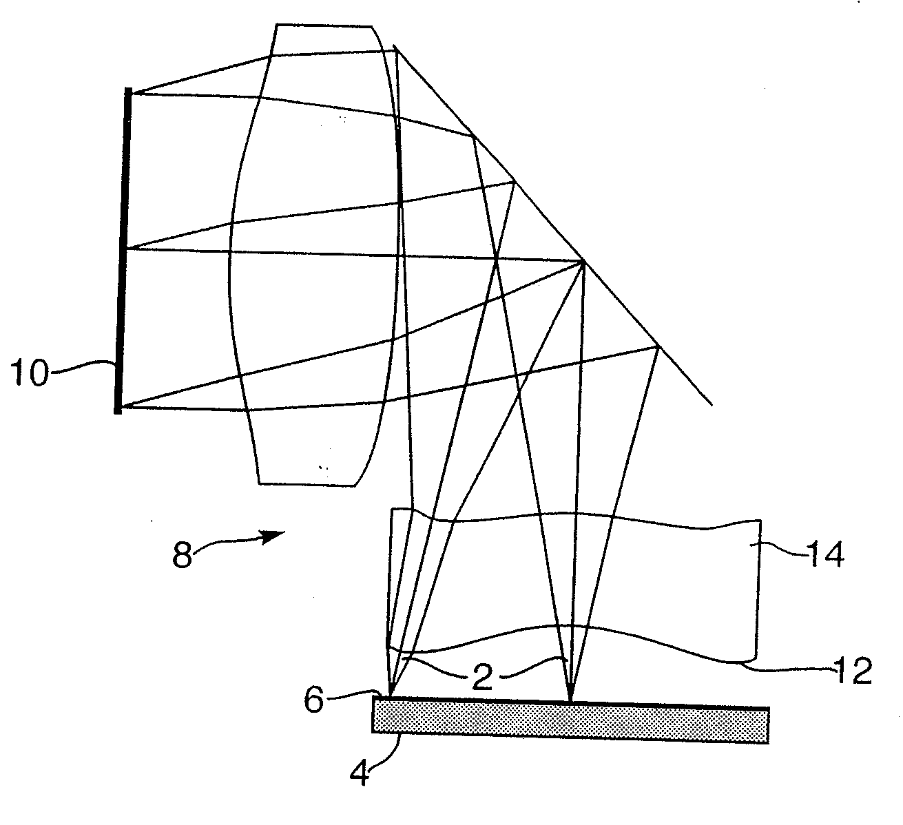
Figure 1 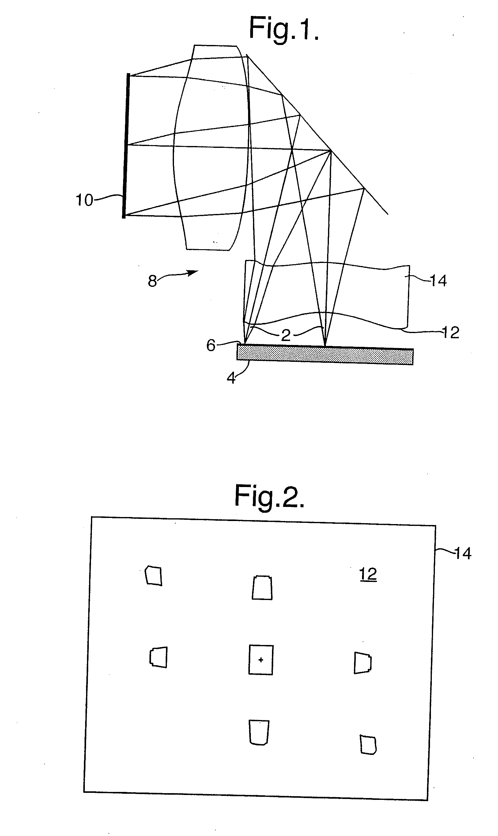
Figure 2 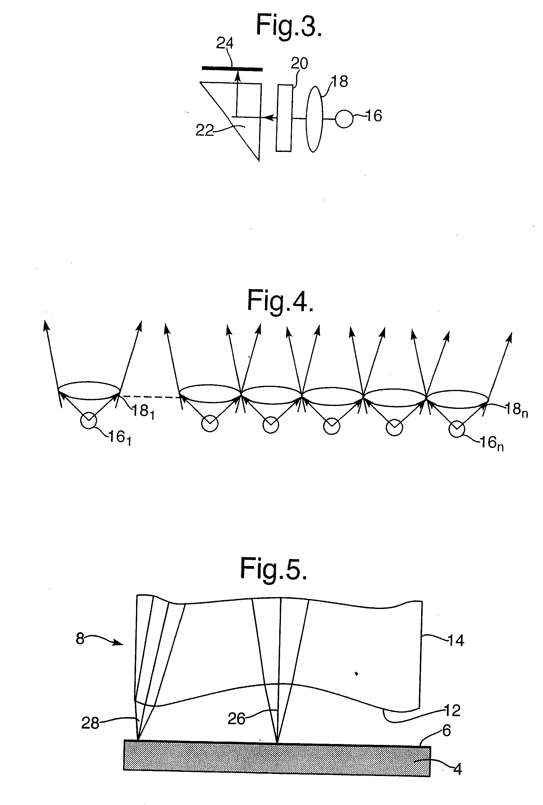
Figure 3
Abstract
Description
CROSS-REFERENCE TO RELATED APPLICATION
[0001] This application is a divisional of application Ser. No. 10 / 937,207, filed Sep. 9, 2004 for HIGH BRIGHTNESS OPTICAL DEVICE which is incorporated herein by reference.FIELD OF THE INVENTION
[0002] The present invention relates to an optical display system and method, and particularly to a display system and method for see-through display applications.
[0003] The invention can be implemented to advantage in a large number of personal imaging applications, such as, for example, head-mounted displays (HMDs) and head-up displays (HUDs), hand-held displays, as well as binoculars, monoculars and binoculars. In addition, the same arrangement can be utilized for image projection systems such as front projectors for conference rooms and rear projection TV screens. BACKGROUND OF THE INVENTION
[0004] One of the important applications for compact optical elements is in HM)s wherein an optical module serves both as an imaging lens and a combiner, in wh...
Examples
Embodiment Construction
[0025]FIG. 1 illustrates an optical display system, wherein light waves 2 emerging from a display source 4 are diffused by a light diffuser 6, that can be an integral part of the display source, such that each light wave which is emerging from a single point in the display source is diverged into a finite solid angle. Usually, a Lambertian light diffusing mechanism is preferred, that is, a diffuser wherein the brightness is constant regardless of the angle from which it is viewed. The light waves are then imaged by an imaging module 8 and illuminate an output aperture 10 of the optical system. For direct view optical systems, this output aperture can be defined as a head-motion-box or an eye-motion-box for a binocular or a monocular respectively, that is, the location where the viewer can see the entire image simultaneously. Alternatively, for see-through optical systems, where the image is projected into the viewer's eye(s) through an optical combiner, the output aperture is define...