
Traveling Vehicle
Patent Information
- Authority / Receiving Office
- US · United States
- Current Assignee / Owner
- Publication Date
- 2009-04-23
- Estimated Expiration
- Not applicable · inactive patent
Smart Images
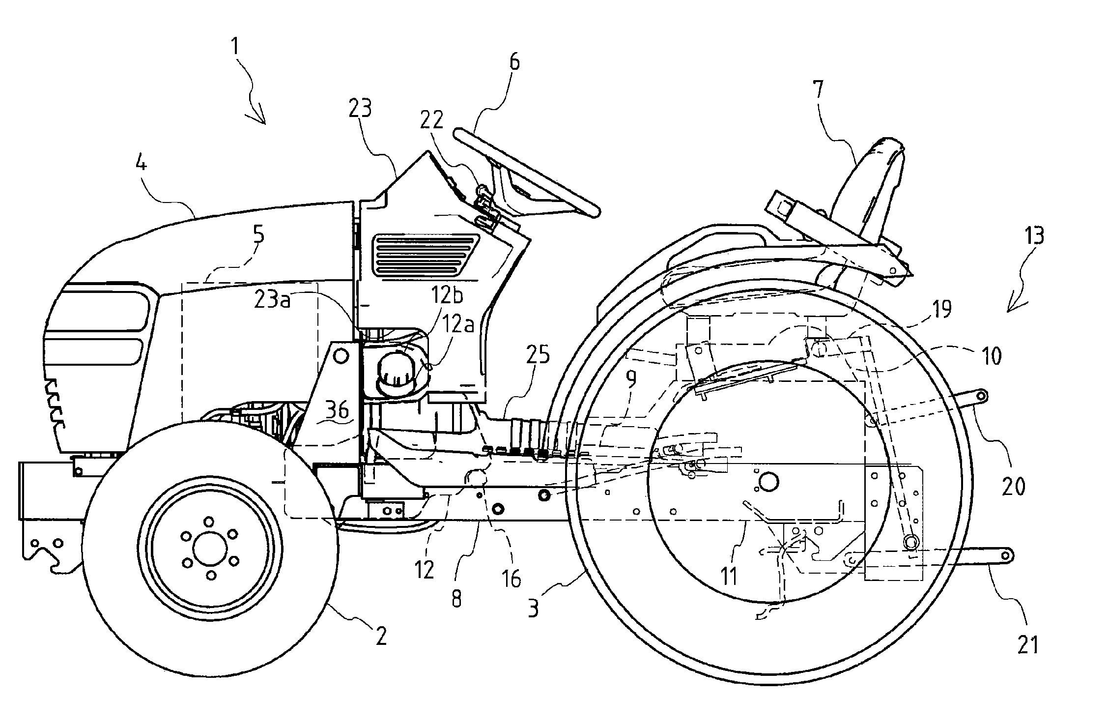
Figure 1 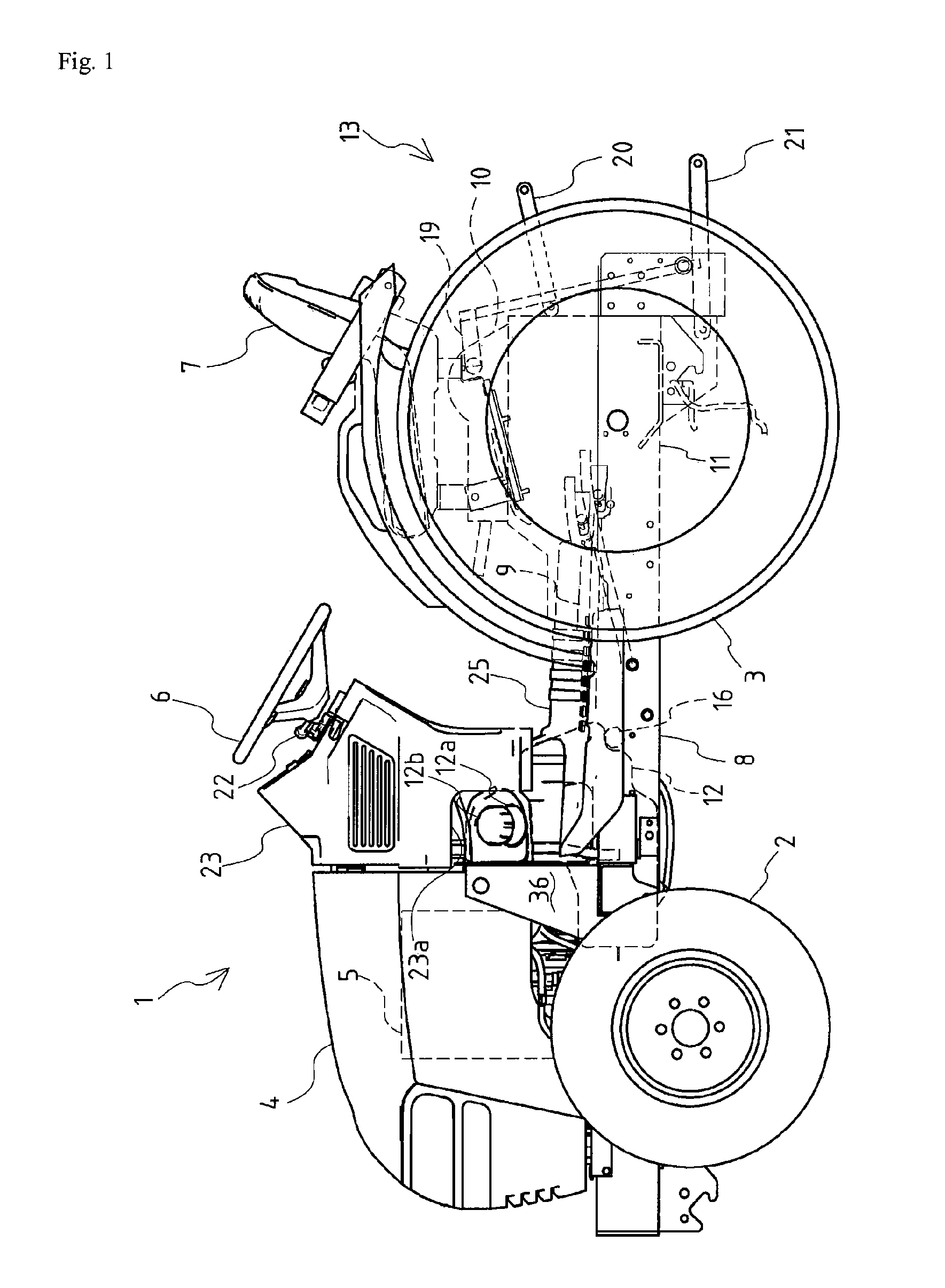
Figure 2 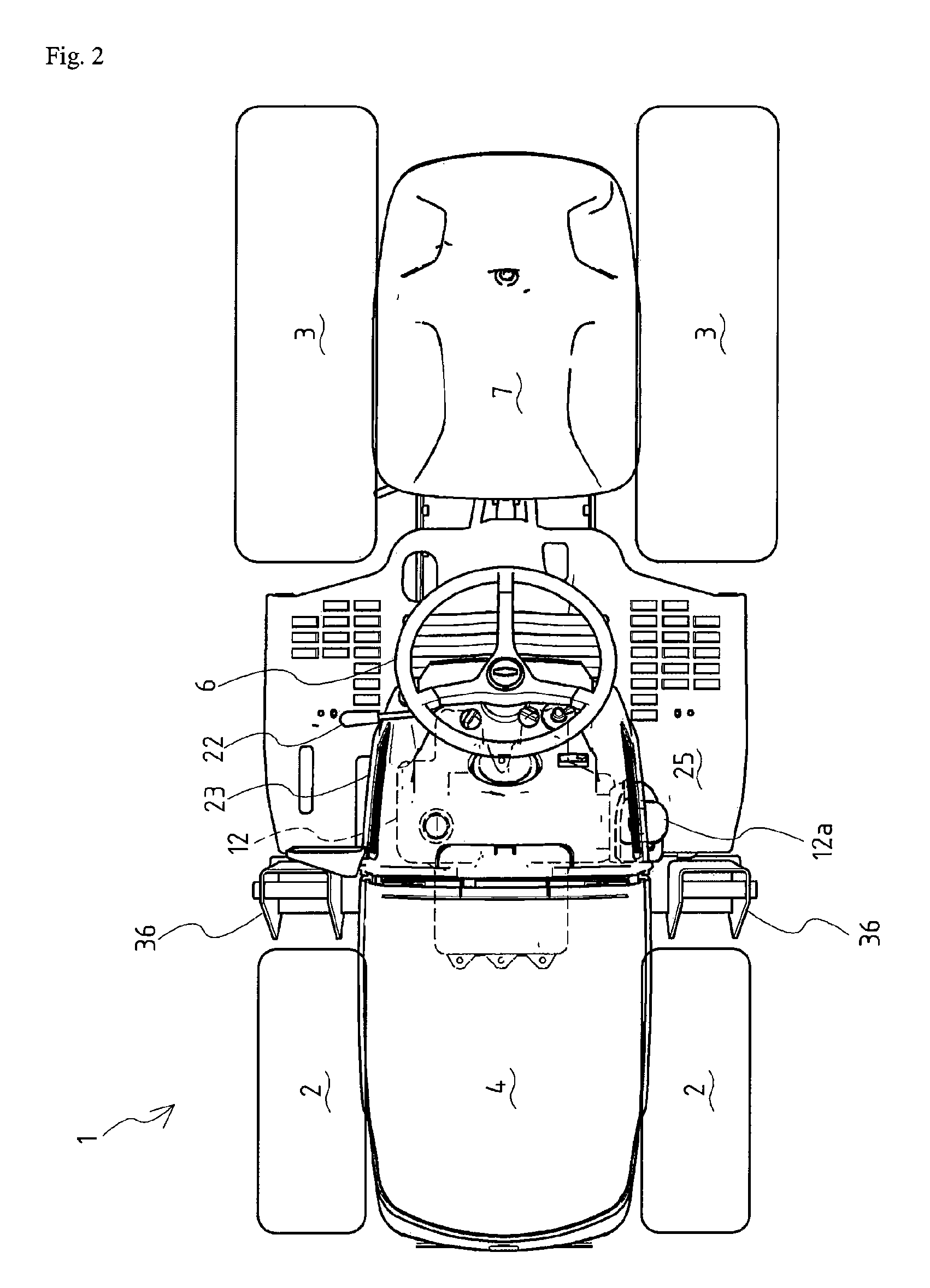
Figure 3
Abstract
Description
TECHNICAL FIELD
[0001] The present invention relates to a traveling vehicle such as a tractor. Especially, the present invention relates to shape and arrangement of a fuel tank mounted on a traveling vehicle and arrangement of a fuel filler of the fuel tank.BACKGROUND ART
[0002] Conventionally, with regard to a traveling vehicle such as a tractor, there is well known structure that a fuel tank is disposed just before a steering wheel at an upper rear portion of a bonnet of the front portion of the traveling vehicle (for example, see the Patent Literature 1). There is also well known structure that a fuel tank is disposed at the rear end of the vehicle body between left and right rear wheels and before a seat (for example, see the Patent Literature 2).
[0003] In resent, structure is proposed that a fuel tank is disposed below a step (for example, see the Patent Literature 3).
[0004] Patent Literature 1: the Japanese Patent Laid Open Gazette Hei. 10-325373
[0005] Patent Literature 2: the Japane...
Examples
Embodiment Construction
[0086]Explanation will be given on an embodiment of the present invention.
[0087]FIG. 1 is a left side view of entire construction of a tractor 1 according to an embodiment of a traveling vehicle of the present invention. FIG. 2 is a plan view of the same. FIG. 3 is a side view of another embodiment of positional relation between a fuel tank 12 and a dashboard 23. FIG. 4 is a perspective rear view of the vicinity of the fuel tank 12. FIG. 5 is a rear view of the fuel tank 12. FIG. 6 is a side view of the same. FIG. 7 is a plan view of the same. FIG. 8 is a perspective upper rear view of the fuel tank 12. FIG. 9 is a perspective upper rear view of support construction of the fuel tank 12. FIG. 10 is a perspective lower rear view of support construction of the fuel tank 12.
[0088]Firstly, explanation will be given on the entire construction of the tractor 1 according to the embodiment of the traveling vehicle of the present invention.
[0089]As shown in FIGS. 1 and 2, with regard to the t...