
Wind generator for installation on a house
Patent Information
- Authority / Receiving Office
- US · United States
- Current Assignee / Owner
- Publication Date
- 2011-12-15
- Estimated Expiration
- Not applicable · inactive patent
Smart Images
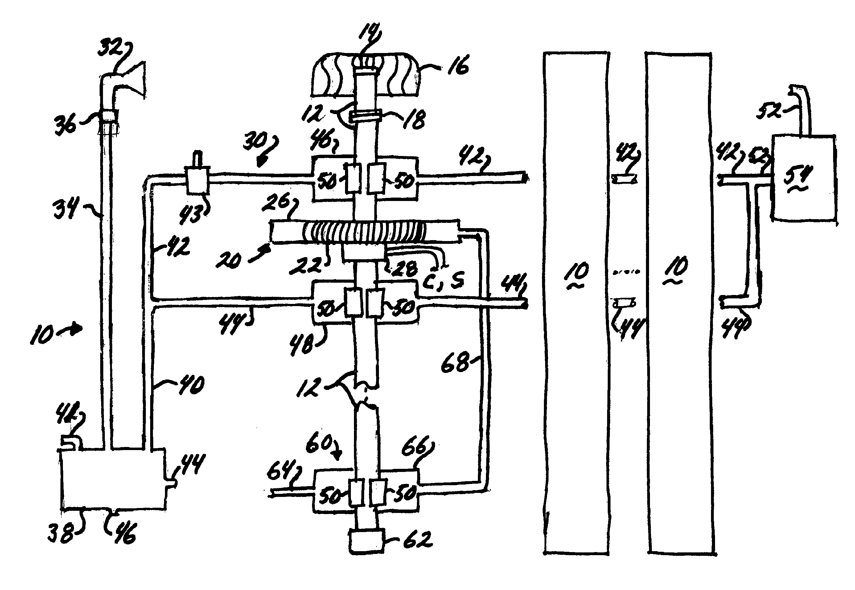
Figure 1 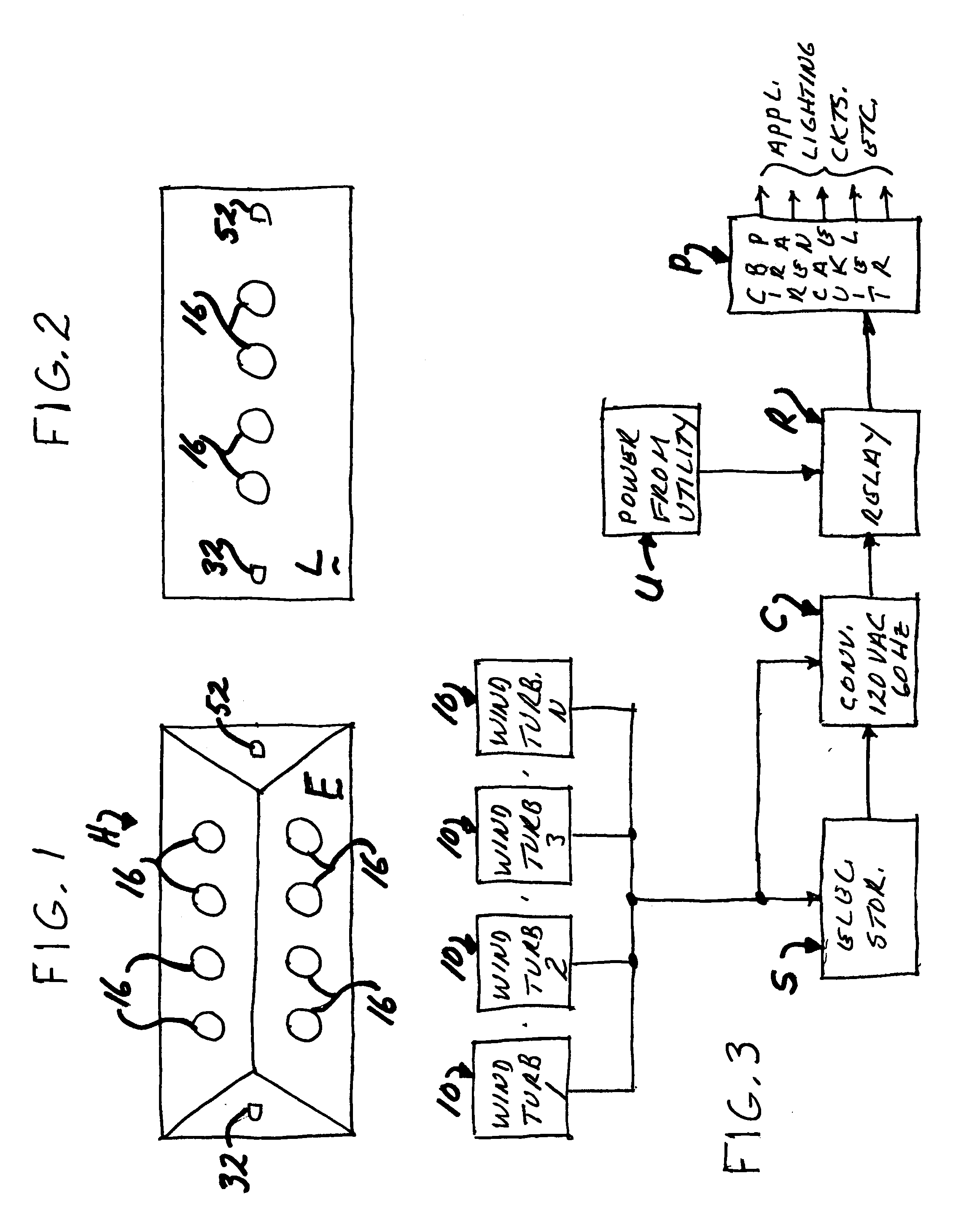
Figure 2 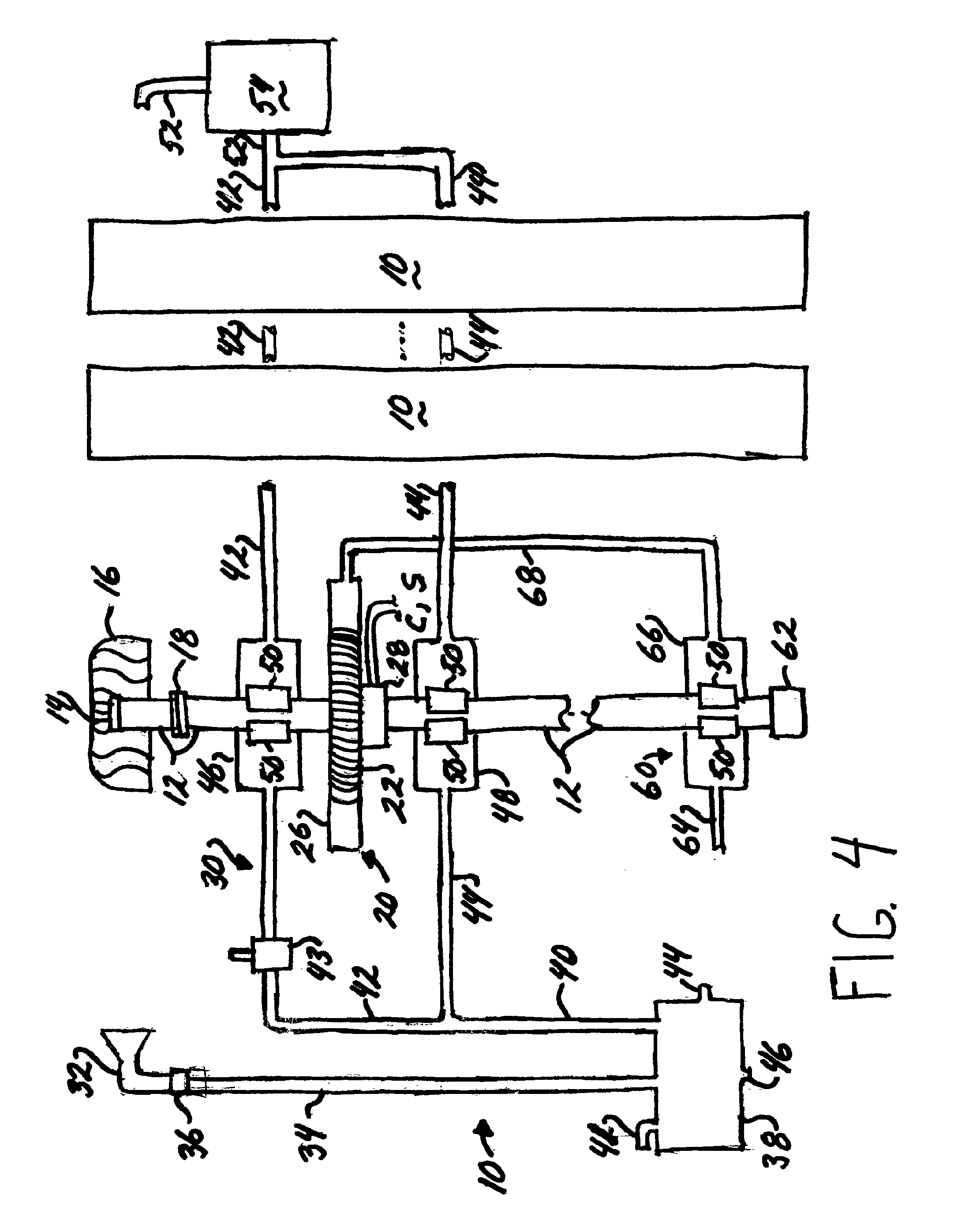
Figure 3
Abstract
Description
CROSS REFERENCE TO RELATED APPLICATIONS
[0001] NoneSTATEMENT REGARDING FEDERALLY SPONSORED RESEARCH OR DEVELOPMENT
[0002] N / ABACKGROUND OF THE INVENTION
[0003] This invention relates to a wind turbine or wind generator for producing electricity; and, more particularly, to a generator for installation on the roof of a house or other small structure.
[0004] Wind turbines or wind generators are known in the art. The typical wind generator comprises a multi-bladed propeller mounted atop a pole and the structure is often referred to as a windmill generator. The propeller rotates in response to wind currents and rotation of a shaft on which the propellers are mounted turn the rotor of an electrical generator and produce electricity. Although many such generators are located on wind farms so a large number of units located in close proximity to each other in a grid produce large amounts of electricity, individual units have been installed adjacent a facility to produce electricity used by the faci...
Examples
second embodiment
[0039]Referring now to FIG. 7, the wind turbine is indicated generally 100. Each turbine 100 includes a coupling 118 connecting an upper section of a shaft 112 connected to a housing 116, and a lower section of the shaft. As with the previously described embodiment, if the wind speed becomes so strong that damage may occur to either the shaft or the housing, coupling 118 disconnects the upper section of the shaft from the housing to prevent damage to the shaft. Again, when the wind speed abates coupling 118 reconnects the two sections of the shaft.
[0040]The electrical generator portion of wind turbine 100 is indicated generally 120 and includes a wire wound rotor 122 mounted on shaft 112 to rotate through an electromagnetic field established in conjunction with magnets housed in an assembly 126. The electric current is drawn off to converter C or storage unit S through a slip ring assembly 128. Again those skilled in the art will understand that the elements comprising electrical ge...
first embodiment
[0049]Finally, reciprocal air intakes 350 are installed about housing 330. These intakes draw air into the housing through a chamber 352 located at the surface of the water. Air drawn in through the intakes is directed to the magnet assembly within housing 330 for the same reasons as discussed with regard to the invention.
[0050]In view of the above, it will be seen that the several objects and advantages of the present disclosure have been achieved and other advantageous results have been obtained.