
Image recording device
Patent Information
- Authority / Receiving Office
- US · United States
- Current Assignee / Owner
- Publication Date
- 2014-09-18
Smart Images
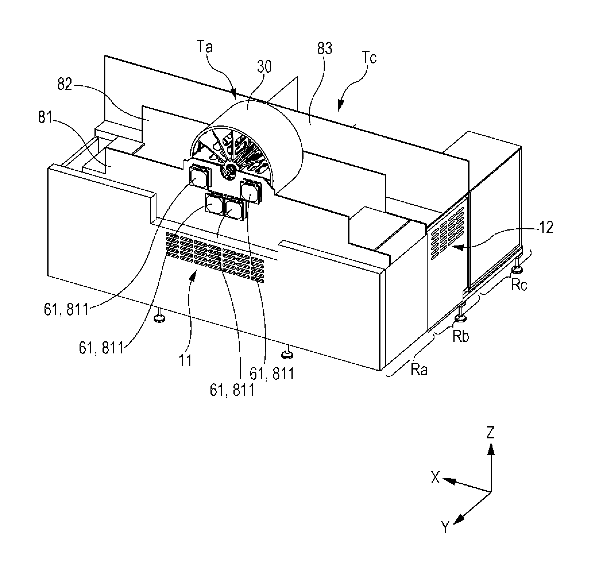
Figure 1 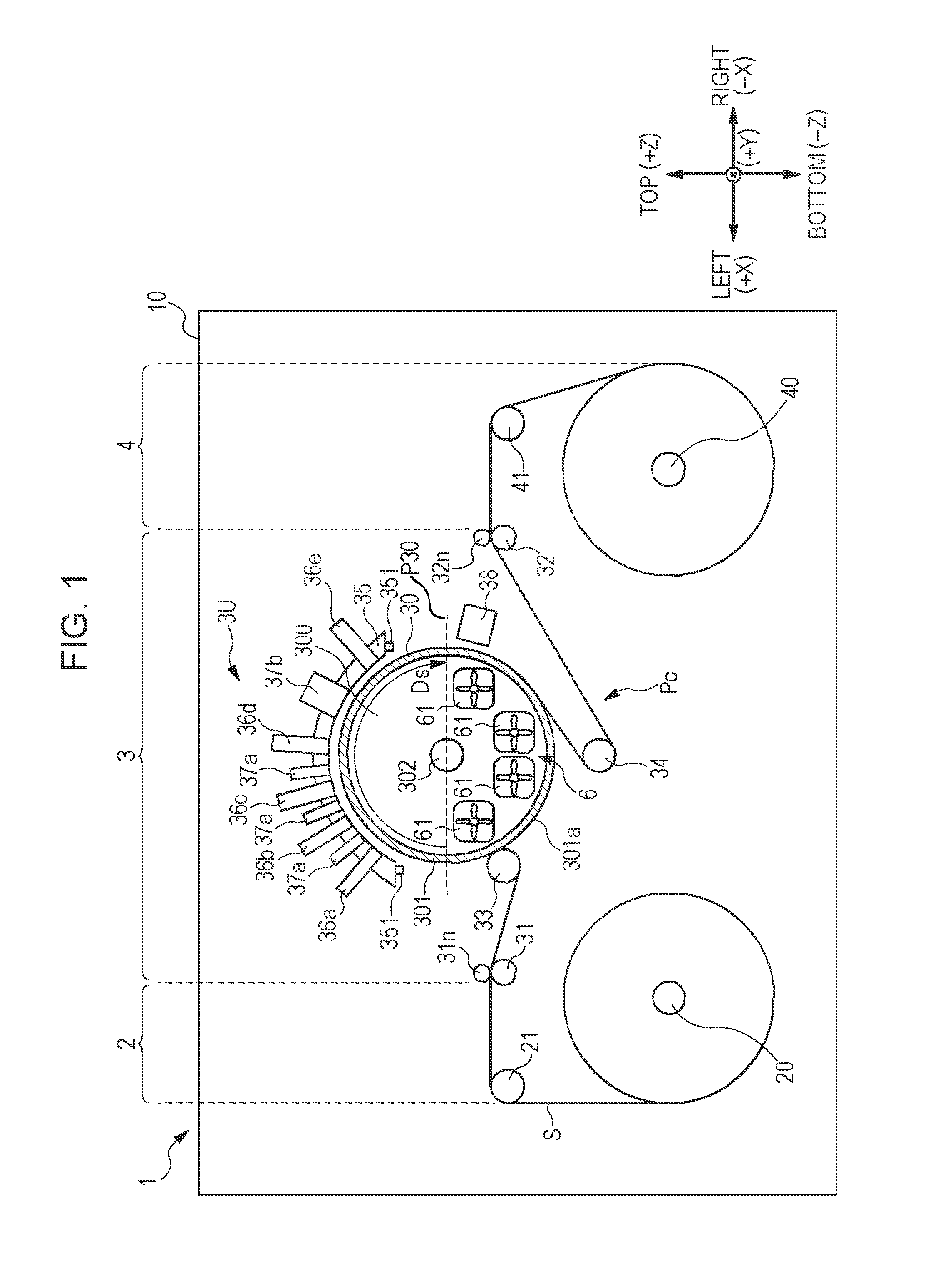
Figure 2 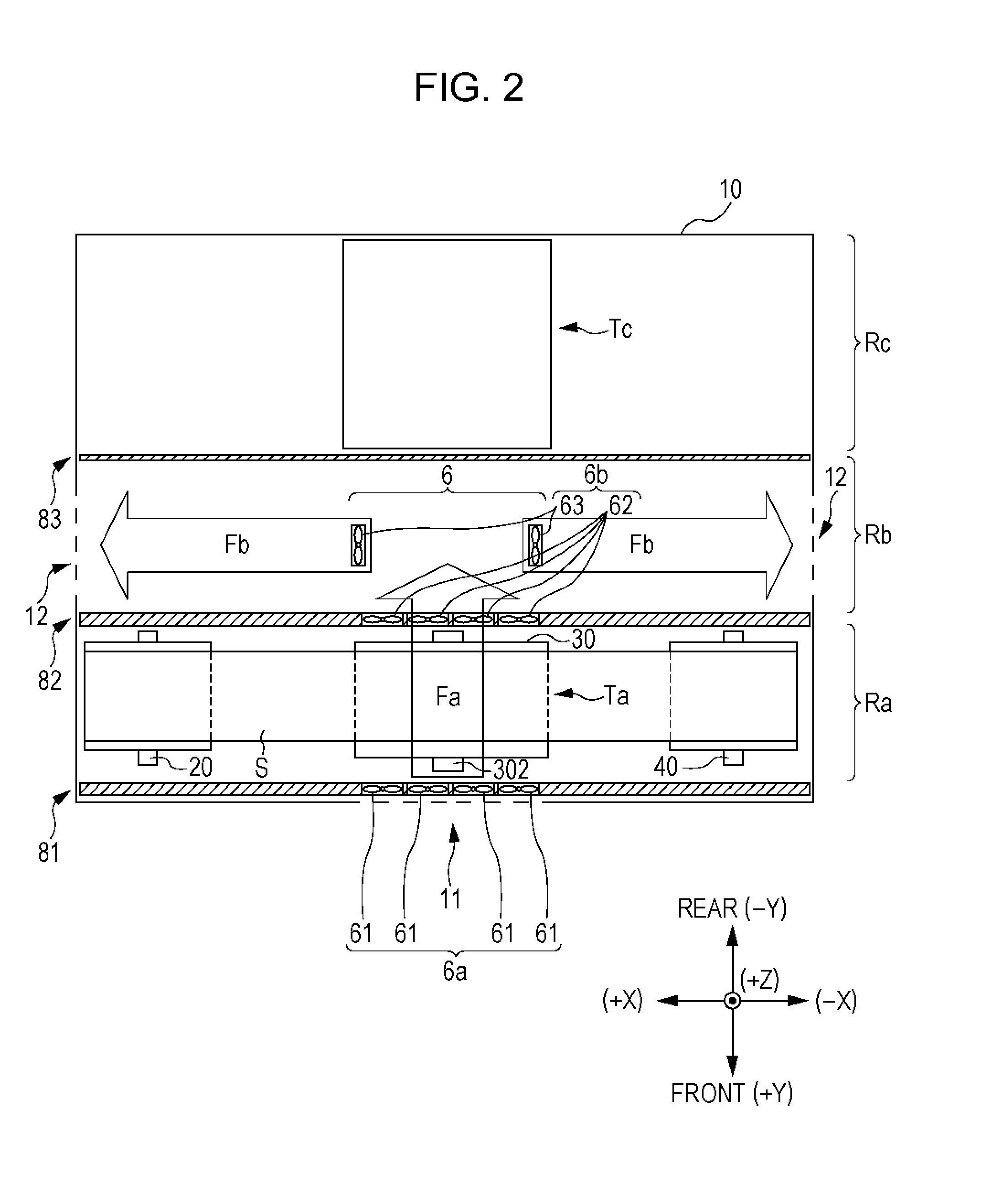
Figure 3
Abstract
Description
BACKGROUND
[0001] 1. Technical Field
[0002] The present invention relates to an image recording device that ejects liquid from an ejecting head onto a recording medium supported on the outer peripheral surface of a rotating drum, and particularly to a technique for cooling the rotating drum.
[0003] 2. Related Art
[0004] U.S. Pat. No. 5,502,476 describes a printer that ejects ink from a print head onto the outer peripheral surface of a drum so as to record an image. In this printer, ink on the drum is cooled and solidified by means of the drum, and then the ink is transferred to a print medium constituting a nip together with the drum, thereby printing an image on the print medium. To cool the ink by means of the drum effectively, the drum is cooled with an airflow generated by a fan. Specifically, the fan axially faces a hollow portion axially penetrating the drum, and generates an airflow that cools the drum while passing through the hollow portion (see FIG. 11).SUMMARY
[0005] Another type o...
Examples
Embodiment Construction
[0027]FIG. 1 is a front view schematically illustrating an outline of a configuration of a printer to which the invention is applicable. FIG. 1 and the following drawings employ an XYZ orthogonal coordinate system including a lateral direction X, a front-to-back direction Y, and a vertical direction Z of a printer 1 in order to clarify the positional relationship among components of the printer as necessary.
[0028]The printer 1 includes a feeder 2, a processor 3, and a winder 4 that are arranged along the lateral direction X and are housed in a housing 10 (an exterior member). The feeder 2 and the winder 4 include a feeder shaft 20 and a winder shaft 40, respectively. A sheet S (a web) is stretched between the feeder shaft 20 and the winder shaft 40 with the two ends of the sheet S being wound into a roll around the feeder shaft 20 and the winder shaft 40. Along a path Pc formed by the stretching, the sheet S is transported from the feeder shaft 20 to the processor 3, subjected to pr...