
Radio receiver
a receiver and radio technology, applied in the field of radio receivers, to achieve the effect of improving reception characteristics
Patent Information
- Authority / Receiving Office
- US · United States
- Patent Type
- Applications(United States)
- Current Assignee / Owner
- Publication Date
- 2009-05-07
Smart Images
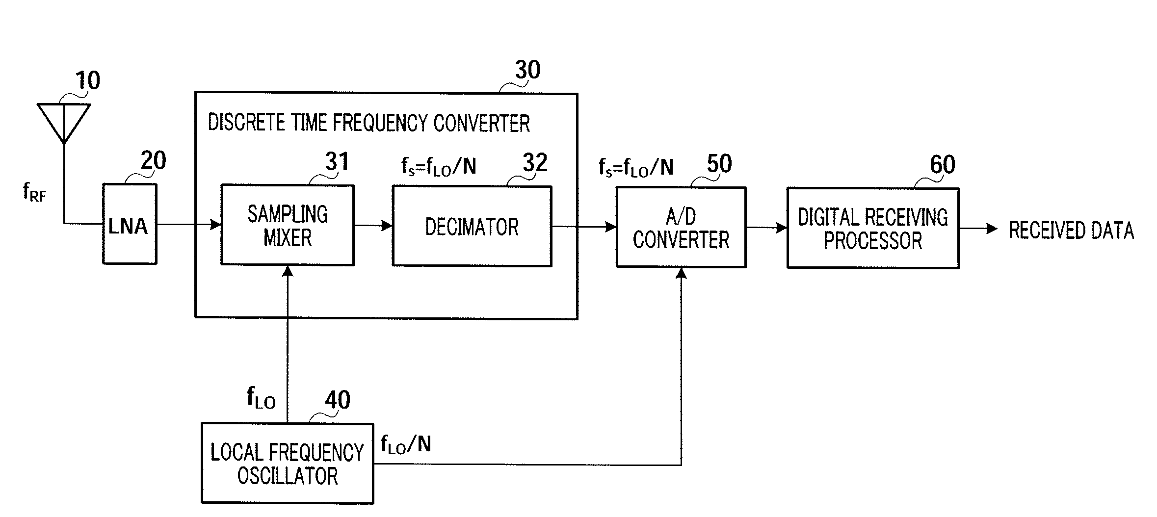
Figure 1 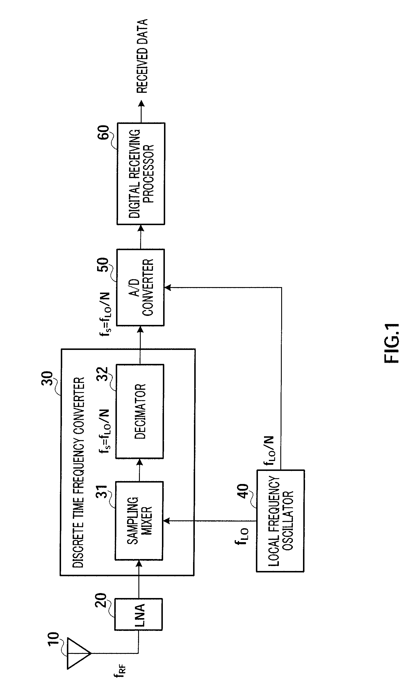
Figure 2 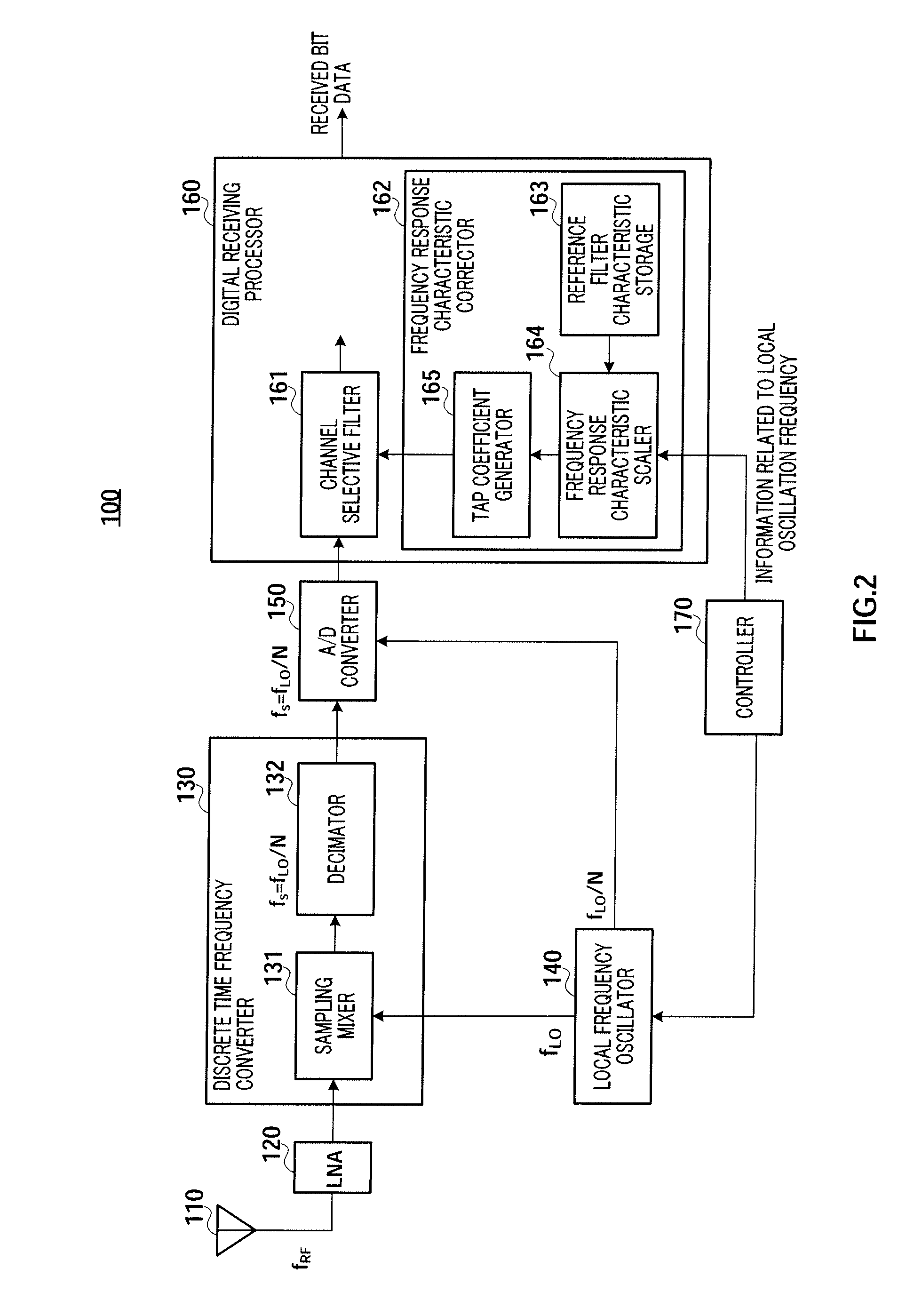
Figure 3
Abstract
Description
TECHNICAL FIELD
[0001] The present invention relates to a radio receiver that samples a high frequency signal at discrete times to perform a discrete time process on the subsequent stage.BACKGROUND ART
[0002] In order to reduce the size and power consumption of a radio receiver or integrate an analog signal processor with a digital signal processor, a configuration that directly samples a high frequency signal at discrete times to perform a discrete time process on the subsequent stage has been proposed (for example, Non-Patent Document 1). This configuration is expected to reduce the design complexity of a continuous-time analog process according to the related art.
[0003] Hereinafter, an example of the configuration and operation of a radio receiver using the discrete time process according to the related art will be described with reference to FIG. 1.
[0004] Analog RF signals received by antenna 10 are amplified by low noise amplifying section (LNA) 20. The amplified analog RF signals ar...
Examples
embodiment 1
[0028]In this embodiment, in a receiving system that performs a discrete time process, the configuration and operation of a DIGITAL RECEIVING PROCESSOR correcting filtered frequency response characteristic, in accordance with the sampling rate, which varies depending on the received channel frequency, using information related to local frequency.
[0029]FIG. 2 is a block diagram showing the configuration of radio receiver 100 according to this embodiment. Radio receiver 100 receives digital modulated signals transmitted at a carrier frequency fRF, performs a predetermined demodulating process on the received signals, and output the resulting received bit data. Radio receiver 100 includes antenna 110, low noise amplifying section (LNA) 120, DISCRETE TIME FREQUENCY CONVERTER 130, LOCAL FREQUENCY OSCILLATOR 140, A / D CONVERTER 150, DIGITAL RECEIVING PROCESSOR 160, and CONTROLLER 170.
[0030]Antenna 110 receives signals that are transmitted at the carrier frequency fRF through a radio propag...
embodiment 2
[0062]This embodiment describes the configuration and operation of a DIGITAL RECEIVING PROCESSOR that has the filtering effect during frequency conversion using a discrete time process and performs a correction filtering process corresponding to a variation in frequency response characteristic, which is caused depending on a received channel frequency by the filtering effect, using information related to a local oscillation frequency.
[0063]FIG. 4 is a diagram showing the configuration of radio receiver 200 according to this embodiment. In radio receiver 200, components having the same operation and configuration as those in radio receiver 100 shown in FIG. 2 are assigned the same reference numerals, and a description thereof will not be repeated, for ease of explanation. Radio receiver 200 differs from radio receiver 100 in the configuration and operation of DECIMATOR 211 in DISCRETE TIME FREQUENCY CONVERTER 210 and CORRECTION FILTER 221 and FREQUENCY RESPONSE CHARACTERISTIC CORRECT...
embodiment 3
[0092]In this embodiment, configuration and operation for further extending the received channel frequency band in the configuration of the radio receiver according to Embodiment 2 will be described below.
[0093]FIG. 6 is a diagram showing the configuration of radio receiver 300 according to this embodiment. In radio receiver 300, components having the same configuration and operation as those in radio receiver 200 shown in FIG. 4 are assigned the same reference numerals, and a detailed description thereof will not be repeated. Radio receiver 300 differs from radio receiver 200 in the configuration and operation of DECIMATOR 311 in DISCRETE TIME FREQUENCY CONVERTER 310 and FREQUENCY RESPONSE CHARACTERISTIC CORRECTOR 321 in DIGITAL RECEIVING PROCESSOR 320 and CONTROLLER 330.
[0094]Further, in this embodiment, it is assumed that a system is allocated with the received channel frequency band of 400 MHz to 800 MHz, and the system corresponds to a channel frequency band lower than that in ...