
Steerable stylet for an implantable medical lead, and method for manufacture thereof
a technology of implantable medical leads and stylets, which is applied in the direction of catheters, diagnostics, applications, etc., can solve the problems of torque coupling between the tube and the actuator, torque limiting devices will release, and torque limiting devices
Patent Information
- Authority / Receiving Office
- US · United States
- Current Assignee / Owner
- Publication Date
- 2009-10-01
Smart Images
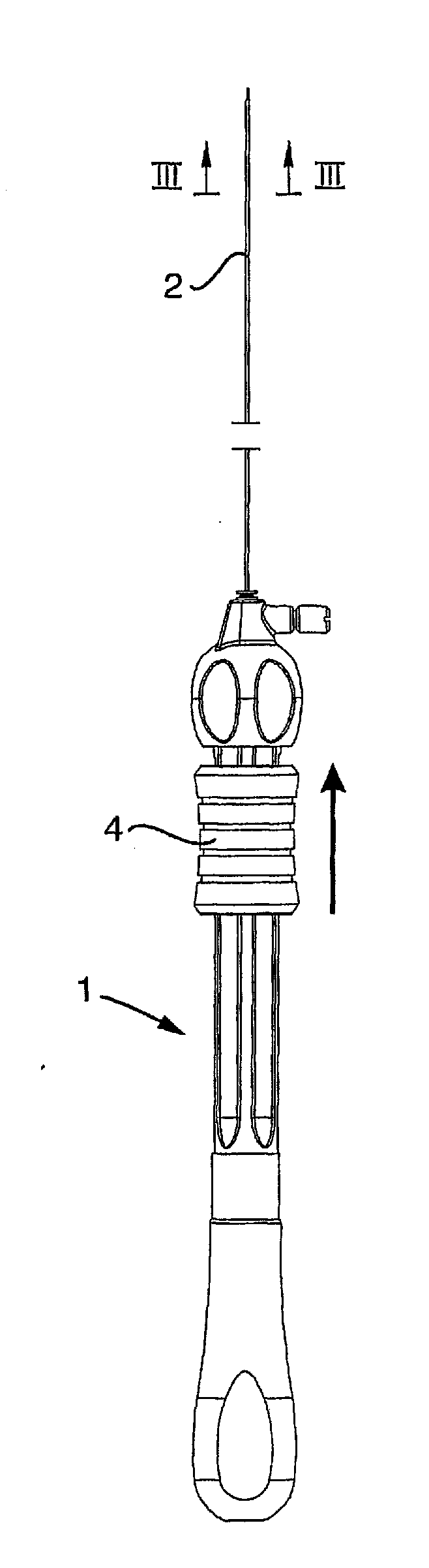
Figure 1 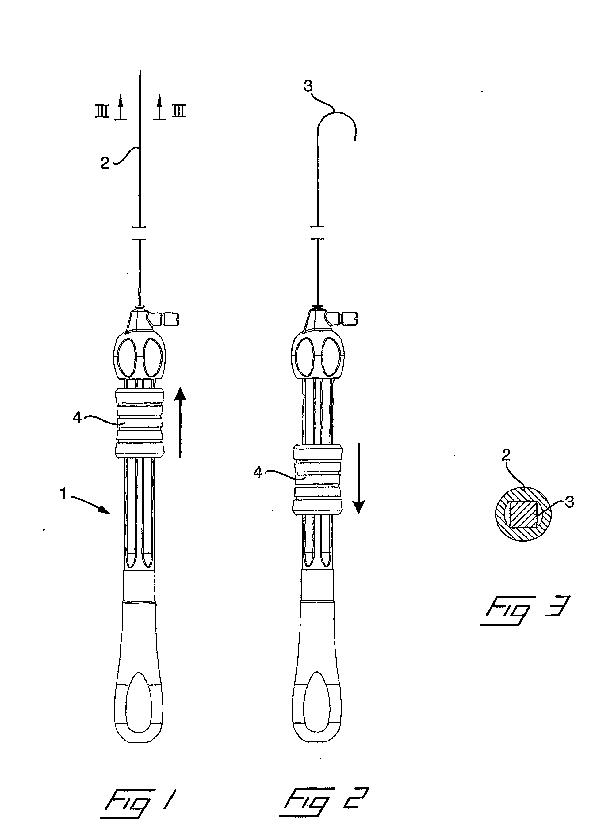
Figure 2 
Figure 3
Abstract
Description
BACKGROUND OF THE INVENTION
[0001] 1. Field of the Invention
[0002] The invention relates to a steerable stylet for a medical implantable lead of the type having an inner lumen, into which the steerable stylet is insertable for navigating a distal end of the medical implantable lead to the desired location for attachment to tissue, the steerable stylet comprising an elastic tube, a likewise elastic wire, being insertable into the tube, and an actuator in a proximal end for manipulating them in relation to each other, wherein the tube and the wire being arranged such that, when the wire is inserted into the tube, the tube and the wire are non-rotatable in relation to each other and at least the wire is pre-bent in one direction such that a distal portion of the steerable stylet, and hence also the medical implantable lead, may be bent in desirable degree by displacing the tube and the wire in relation to each other such that a portion of the wire protrudes from the distal end of the tube...
Examples
first embodiment
[0031]In FIG. 9 is shown a perspective view in an enlarged scale, of the tube 2, the tube shaft 6, the carrier element 7 and the torque limitation device 8. In this embodiment the torque limitation device comprises a break pin 15, which is held by a bracket support 16 and is extended into a recess in the carrier element 7. As is mentioned before, the carrier element is rotatable around the tube shaft 6 but as long as the break pin 15 connects the carrier element and the bracket support 16, which is rigidly connected to the tube shaft 6, any rotationally movement of the actuator handle 1 will be transmitted via the carrier element 7, the brake pin 15, the bracket support 16 and the tube shaft 6 to the tube 2 such that it can participate in pivoting the distal end of the stylet and the lead 5.
[0032]In FIG. 10 is illustrated a case when the torque limit for the torque limitation device 8 has been exceeded and the break pin 15 has been broken. Now the tube shaft 6 and the tube 2 are fre...
second embodiment
[0033]In FIG. 11 is shown a corresponding perspective view in an enlarged scale, of the torque limitation device 8. In this embodiment the torque limitation device comprises a ball 17, which is held by the bracket support 16 and is forced towards a recess in the carrier element 7 by means of a spring 18. As long as the ball 17 is in engagement with the recess in the carrier element 7, any rotationally movement of the actuator handle 1 will, in a corresponding way as the embodiment in FIGS. 9 and 10, be transmitted via the carrier element 7, the ball 17, the bracket support 16 and the tube shaft 6 to the tube 2 such that the tube can participate in pivoting the distal end of the stylet and the lead 5.
[0034]In FIG. 12 is illustrated a corresponding case when the torque limit for the torque limitation device 8 has been exceeded and the ball 17 has been forced out of engagement of the recess in the carrier element. Now the tube shaft 6 and the tube 2 are free to rotate independently of ...