
Sound maximizing ammellescope
Patent Information
- Authority / Receiving Office
- US · United States
- Current Assignee / Owner
- Publication Date
- 2010-07-01
- Estimated Expiration
- Not applicable · inactive patent
Smart Images
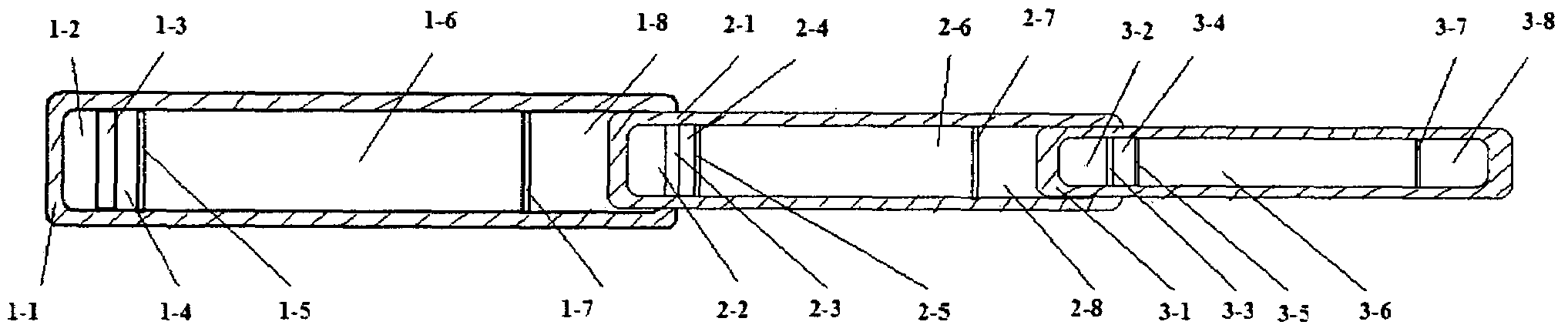
Figure 1 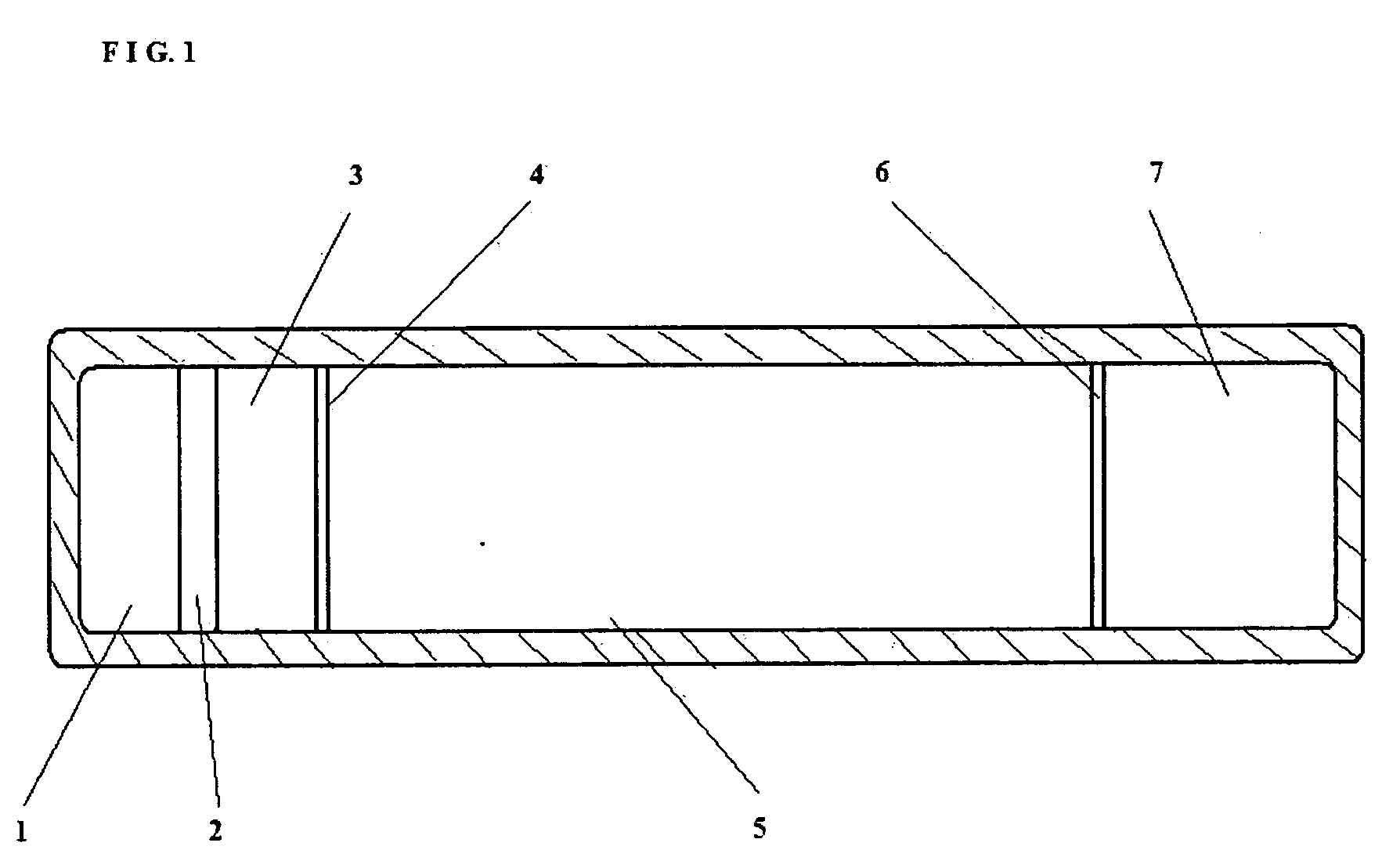
Figure 2 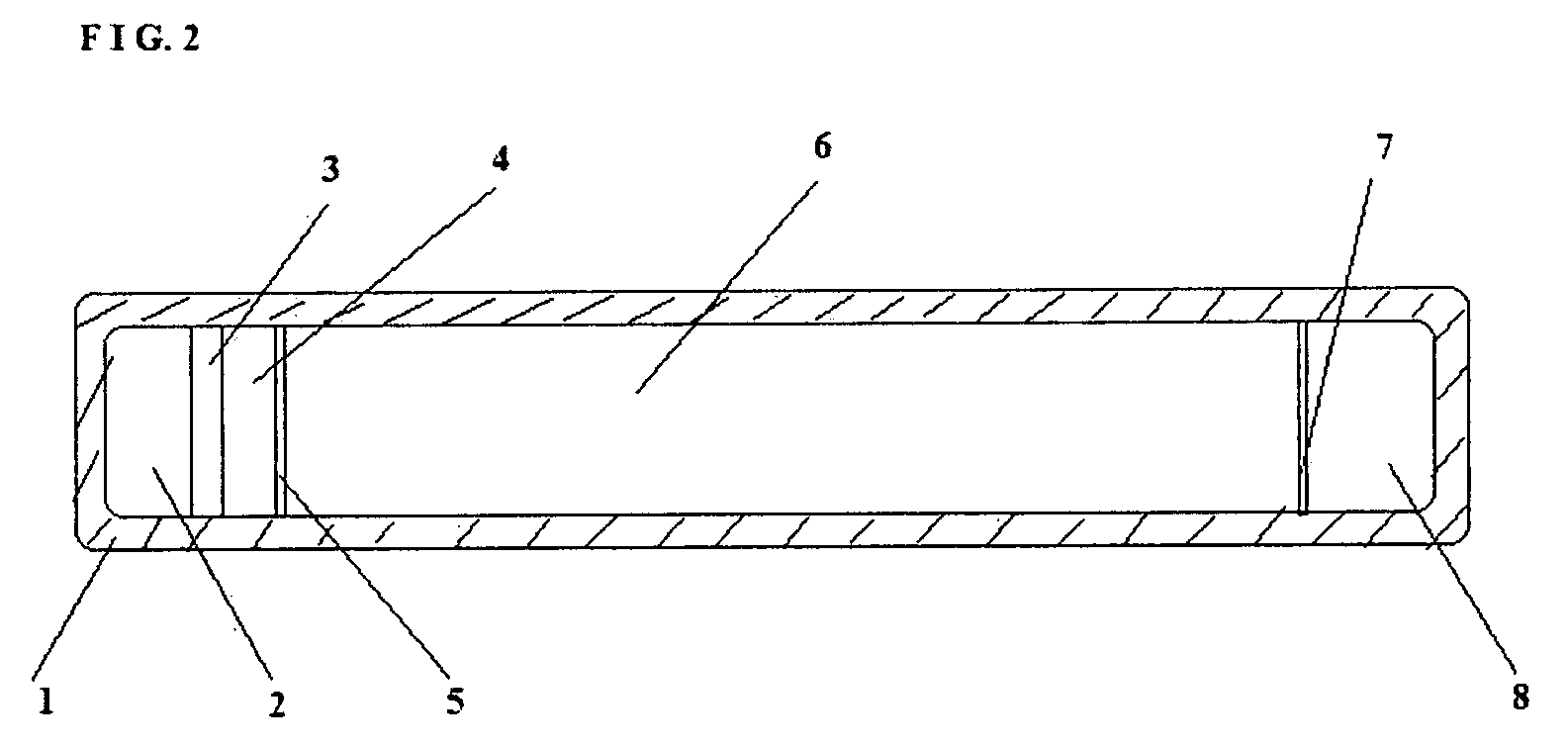
Figure 3
Abstract
Description
BACKGROUND OF THE INVENTION
[0001] 1. Field of the Invention
[0002] This invention relates to a hand hold device that receives sound wave, which then be magnified to be heard by human ear. Device operator slides the chambers to change the air density in each chamber and the density ratio between two adjacent chambers.
[0003] 2. Description of the Background Art
[0004] The invention of battery free sound magnifier devices has become a challenging journey. Apparatus such as telephone, microphone, and hearing aid devices could only process sound that can be heard by human ear. It limited the invention to electrical signal processing. It provided a challenge to inventors, however, i.e. weak sound which is generated from miles away and which populates to a human ear by air molecules can not be heard or processed by these devices.
[0005] For example, the humming sound produced by a hovering insect can be heard from 2 meters in a quiet environment by human ear. It can, however, be heard by some anim...
Examples
first embodiment
[0018]Device holder press Chamber 1 to his / her ear. Chamber 1 contains chip 1-3 which has multiple small holes to amplify the sound wave. It contains membrane 1-5 which works together with membrane 1-7 to compress the air inside Chamber 1 and between them.
second embodiment
[0019]Device holder press Chamber 2 against Chamber 1. Chamber 2 contains chip 2-3 which has multiple small holes to amplify the sound wave. It contains membrane 2-5 which works together with membrane 2-7 to compress the air inside Chamber 2 and between them.
third embodiment
[0020]Device holder press Chamber 3 against Chamber 2. Chamber 3 contains chip 3-3 which has multiple small holes to amplify the sound wave. It contains membrane 3-5 which works together with membrane 3-7 to compress the air inside Chamber 3 and between them.
[0021]Three chambers work together form air compression ratios between 1-6 and 2-6, and between 2-6 and 3-6. Air is prefilled in the space 1-6, 2-6, 3-6. These three air bodies contain air molecules that will react to pressure and to sound wave vibration. When the air molecules are under higher pressure, they are more active and then populate sound wave at a faster rate and higher quality.
[0022]Weak sound from long distance travels faster in 2-6 than in 3-6, even faster in 1-6 than in 2-6. Air molecules in 2-6 are more active than those in 3-6. Air molecules in 1-6 are more active than those in 2-6.
[0023]For example, the device operator slides Chamber 3, i.e., 3-1 body inward to Chamber 2, i.e., 2-1 body. The air pressure ratio ...