
Board connecting connector
a technology for connecting connectors and motherboards, applied in the direction of coupling device connection, coupling parts engagement/disengagement, printed circuits, etc., can solve the problems of difficult miniaturization of motherboards or motherboard housings and space saving
Patent Information
- Authority / Receiving Office
- US · United States
- Current Assignee / Owner
- Publication Date
- 2010-09-30
- Estimated Expiration
- Not applicable · inactive patent
Smart Images
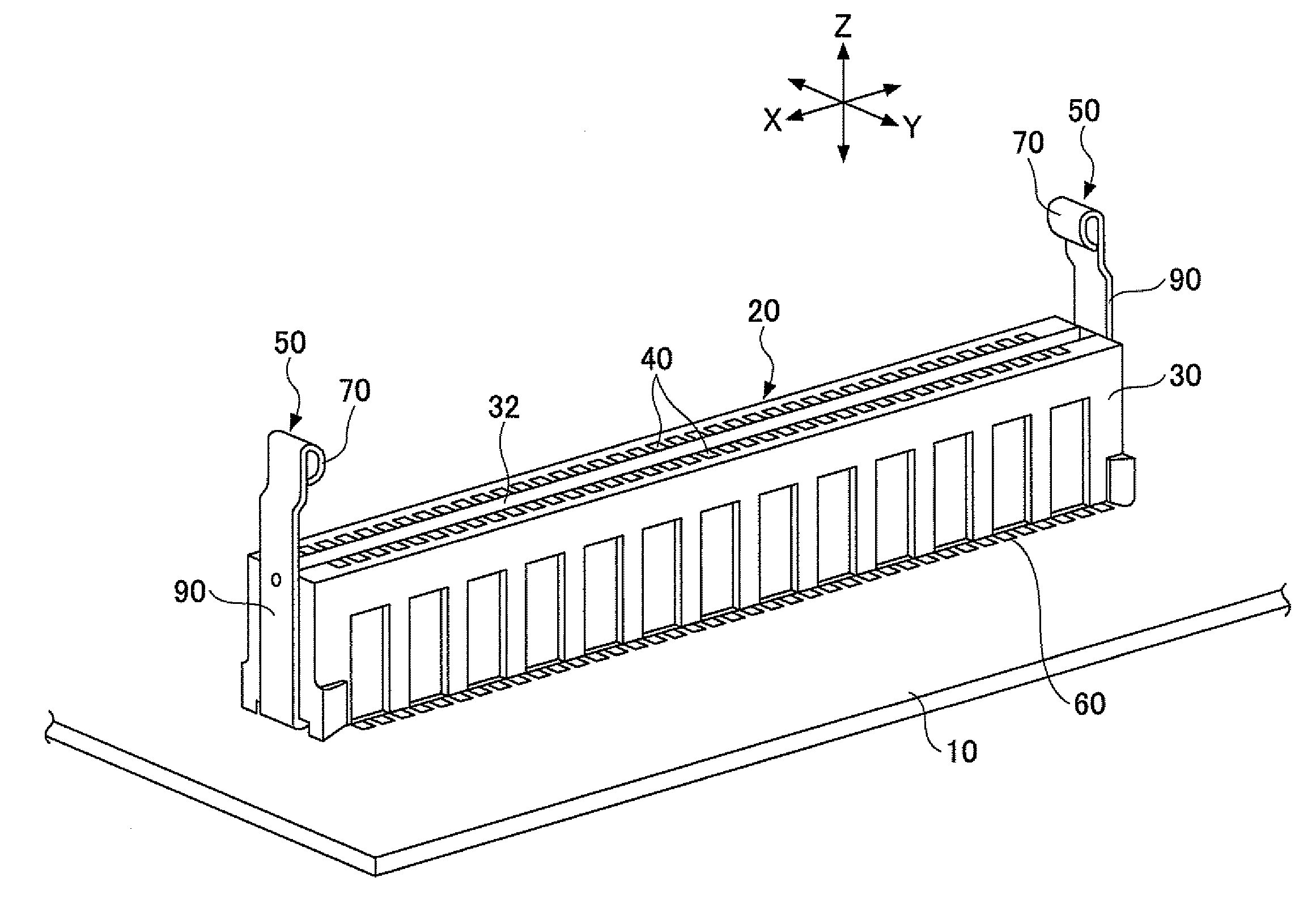
Figure 1 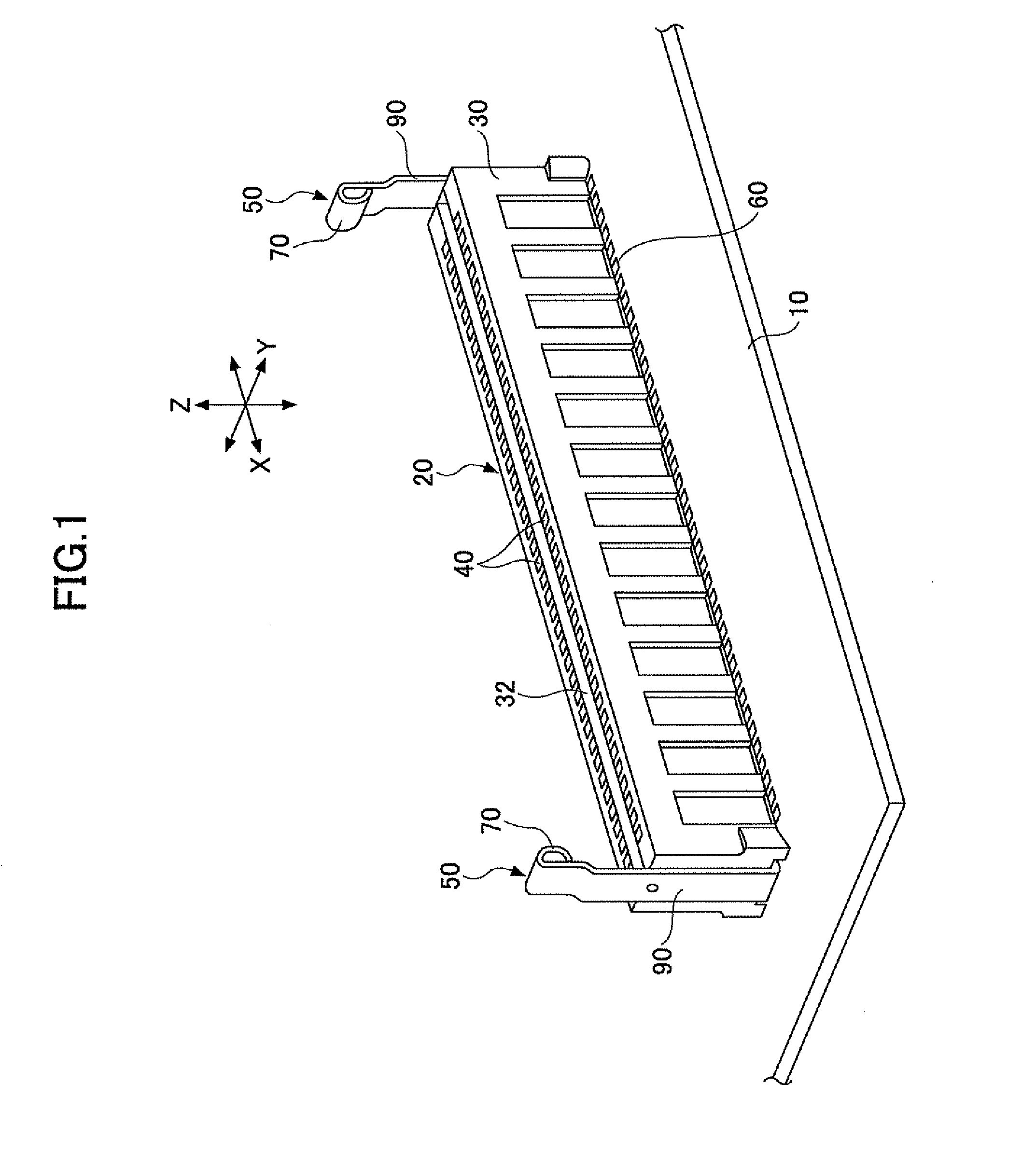
Figure 2 
Figure 3
Abstract
Description
CROSS-REFERENCE TO RELATED APPLICATIONS
[0001] This patent application is based upon and claims the benefit of priority of Japanese Patent Application No. 2009-072697 filed on Mar. 24, 2009 the entire contents of which are incorporated herein by reference.BACKGROUND OF THE INVENTION
[0002] 1. Field of the Invention
[0003] The present invention generally relates to connectors for connecting boards. More specifically, the present invention relates to a connecting board connector, the connector being where the board is inserted.
[0004] 2.Description of the Related Art
[0005] In an electronic apparatus such as a personal computer or a server, as a structure where a circuit having an electronic component such as a memory or an IC chip is often established, a structure described in, for example, Japanese Laid-Open Patent Application Publication No. 10-177080 has been suggested. In this structure, a board is inserted into a connecting board connector mounted on a motherboard to make electrical conne...
Examples
embodiment 1
[0033]FIG. 1 is a perspective view showing an example of a connecting board connector of an embodiment of the present invention. As shown in FIG. 1, a connector 20 for connecting a board is mounted on an upper surface of a motherboard 10. The motherboard 10 is, for example, installed in an electronic apparatus such as a personal computer, a server, or the like. The connector 20 is, for example, a card edge connector. The connector 20 is an expansion connector where an expansion board (another board, mounting board) with an electronic component such as an IC chip or IC memory mounted is inserted.
Structure of Connector 20
[0034]The connector 20 includes a connector main body 30, plural connector pins 40, and a pair of board holding members 50.
[0035]The connector main body 30 is made by molding with a resin material having insulation. A lower surface (one end) of the connector main body 30 is fixed to the motherboard 10. An inserting opening 32 is provided at an upper surface (another e...
modified examples
[0082]Here, modified examples are discussed.
[0083]FIG. 7 is a vertical cross-sectional view showing a modified example 1 of the board holding member. In FIG. 7, parts that are the same as the parts shown in FIG. 6B are given the same reference numerals, and explanation thereof is omitted.
[0084]As shown in FIG. 7, an engaging portion 70A of a board holding member 50A of the modified example 1 is formed in a trapezoidal shape. The engaging portion 70A includes inclination parts 72A and 74A coming in contact with corner parts 102a and 102b, respectively, of the concave part 102.
[0085]The lower end corner part 106 of the expansion board 100 comes in contact with an upper side inclination part 74A of the engaging portion 70A with an inserting operation of the expansion board 100. In addition, the expansion board 100 is pressed downward so that the upper side inclination part 74A of the engaging portion 70A is pressed sideward (in the C direction) so that the elastic arm part 90 is elasti...