
Heatsink-Less Electronic Unit
a technology of electronic units and heat sinks, applied in the direction of printed circuit aspects, electrical apparatus construction details, printed circuit associations, etc., can solve the problems of thermal interference of heating components such as semiconductor relays mounted in electronic units, reaching very high temperature locally, requiring space for installing heat radiating components, and requiring cost for heat radiating components. , to achieve the effect of reducing the cost of heat radiating components, and reducing the cost of heating components
Patent Information
- Authority / Receiving Office
- US · United States
- Patent Type
- Applications(United States)
- Current Assignee / Owner
- Publication Date
- 2015-11-19
Smart Images
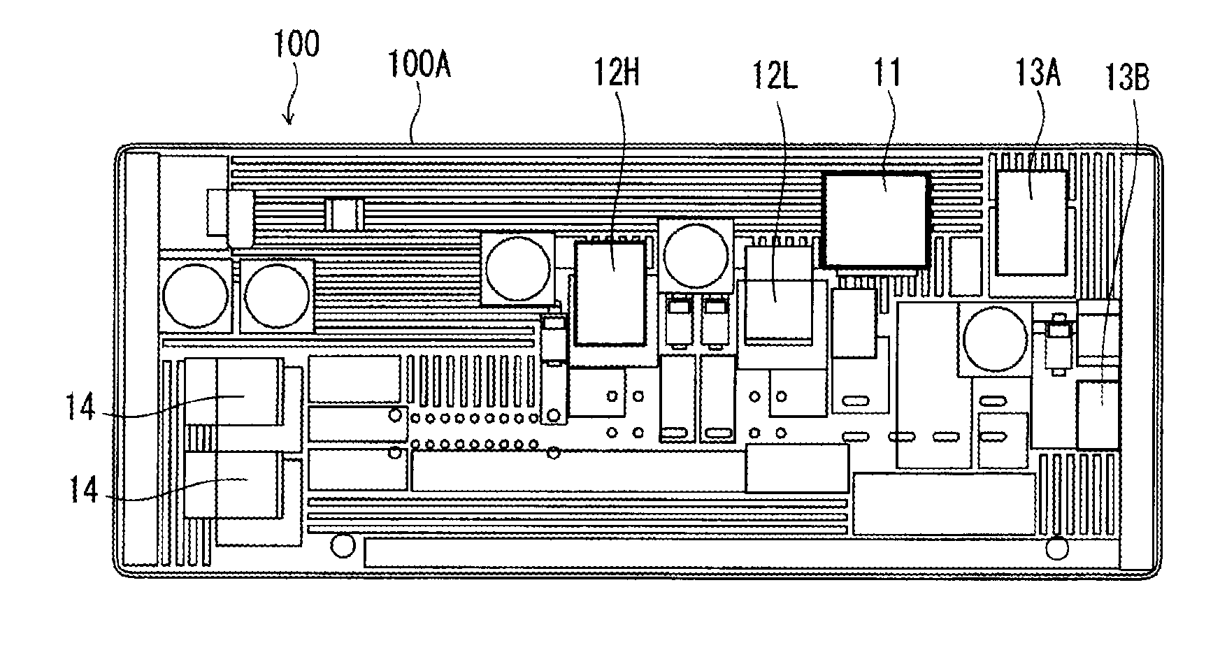
Figure 1 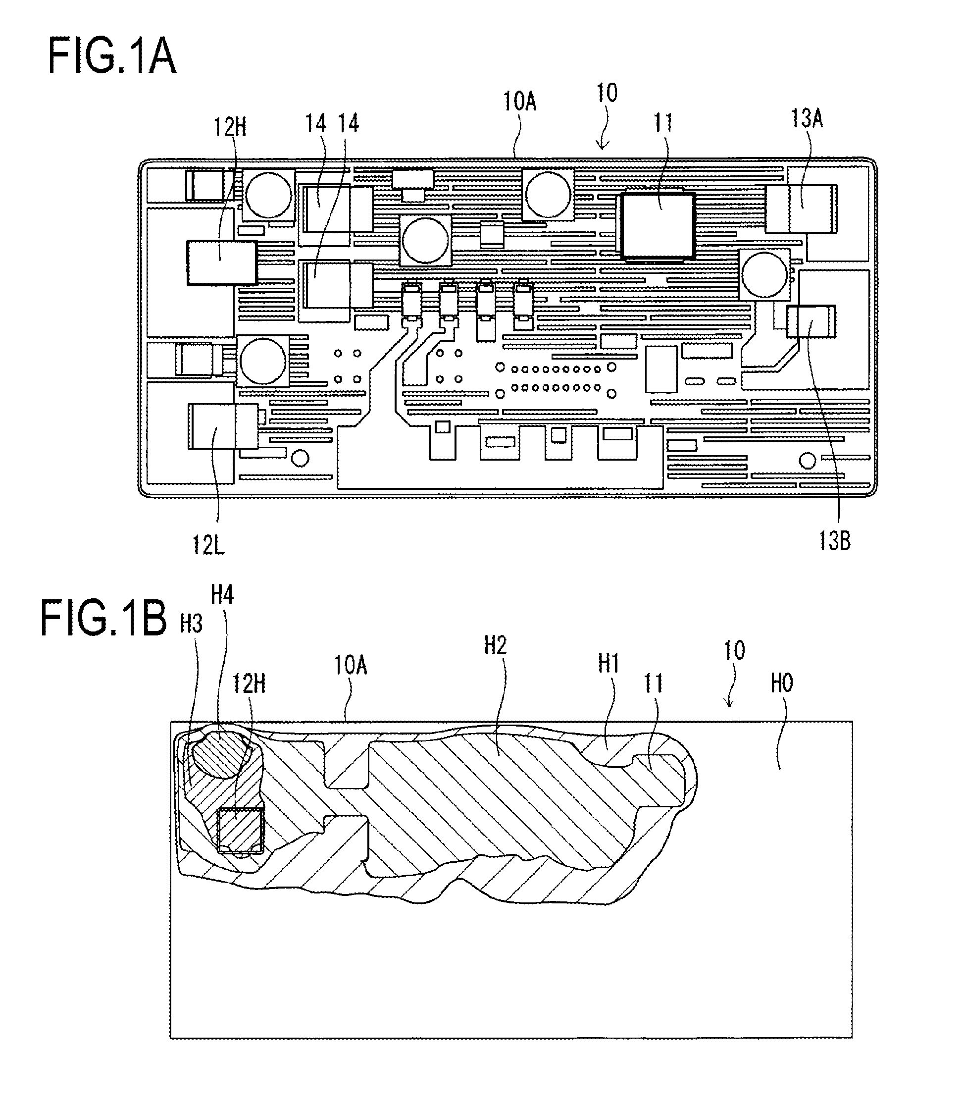
Figure 2 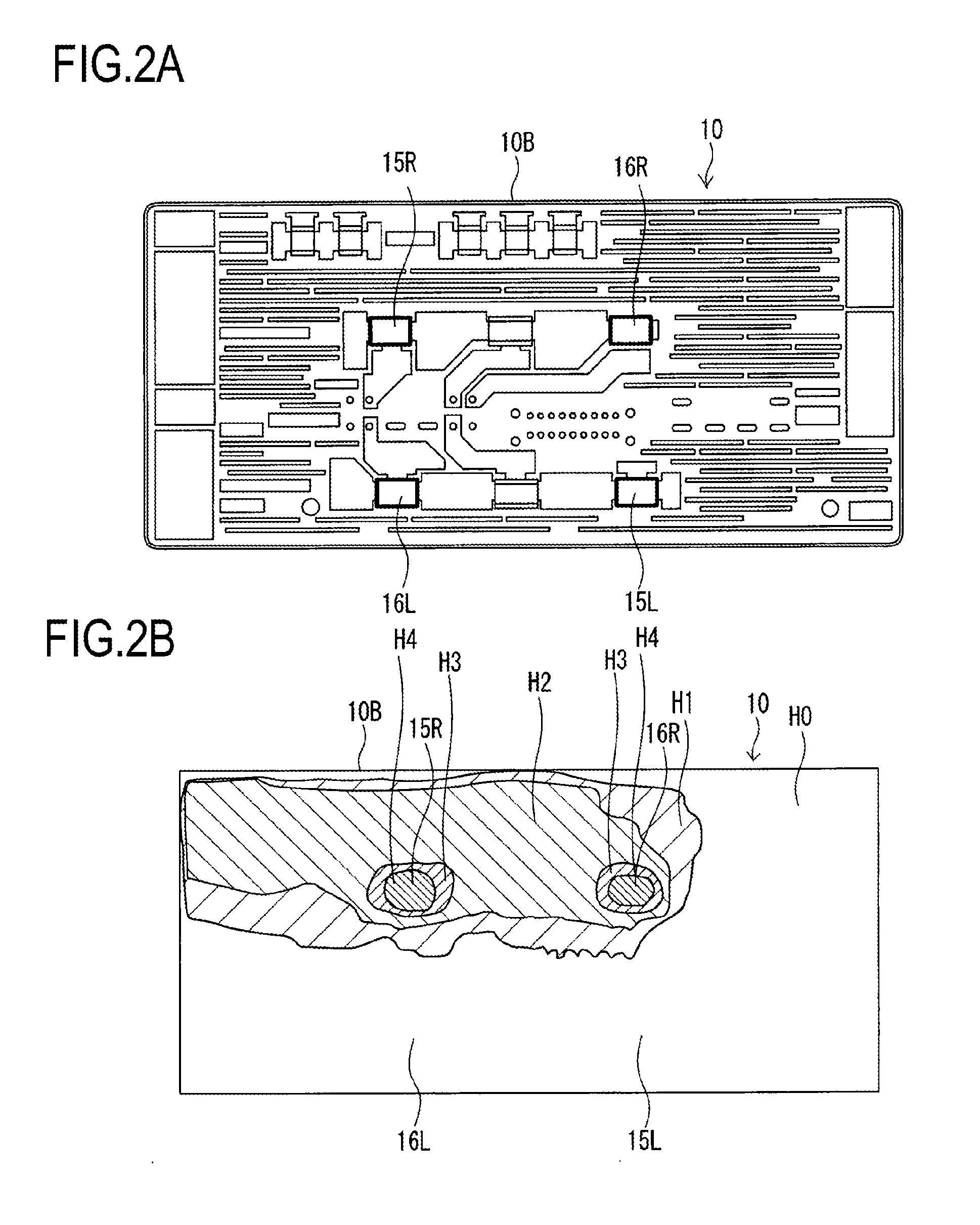
Figure 3
Abstract
Description
CROSS REFERENCE TO RELATED APPLICATIONS
[0001] This application is a continuation of PCT application No. PCT / JP2014 / 052091, which was filed on Jan. 30, 2014 based on Japanese Patent Application (No. P2013-016196) filed on Jan. 30, 2013, the contents of which are incorporated herein by reference.BACKGROUND OF THE INVENTION
[0002] 1. Technical Field
[0003] The present invention relates to an electronic unit which is mounted on a vehicle such as a car and which can be achieved without using any heatsink.
[0004] 2. Background Art<Background-Art Measure Against Heat Radiation>
[0005] Recently, an electronic unit mounted on a vehicle is requested to be miniaturized due to the limitation of an installation space. In some cases, a plurality of heating components such as semiconductor relays mounted in the electronic unit may thermally interfere with one another and reach very high temperature locally. In order to prevent any electronic component or any electronic substrate from exceeding its up...
Examples
embodiment 1
Basic Concept of Embodiment 1
[0020]Power losses of semiconductor relays mounted in a heatsink-less electronic unit can be calculated in advance from flowing currents or internal resistances of electronic components.
[0021]In addition, a combination of semiconductor relays which may reach highest temperature easily can be known if it is considered what running situation (running in the daytime or the nighttime and running during fine weather or during rainy weather) of a vehicle leads to current conduction to various semiconductor relays.
[0022]In addition, it is a matter of course that semiconductor relays to be turned ON for a long time, semiconductor relays to be turned ON for a short time, and semiconductor relays to be turned ON / OFF intermittently can be grasped at the time of design.
[0023]In light of these conditions, it has been made clear that any electronic component or any electronic substrate can be prevented from exceeding its upper limit of allowable temperature even witho...
embodiment 2
Basic Concept of Embodiment 2
[0039]A heatsink-less electronic unit 20 mounted on a vehicle is required to be miniaturized due to the limitation of an installation space. A multilayer insulating plate Z is often used as an electronic substrate (metal coreless electronic substrate provided with three or more layers of copper foil conductive patterns) 20A. For example, consider that the electronic substrate 20A has six layers of copper foils as shown in FIG. 5A and FIG. 5B. In this case, the respective layers of the electronic substrate 20A are often functionally classified as follows.
(1) The first layer C1 and the sixth layer C6 are for mounting of electronic components, arrangement of signal lines, arrangement of output current conducting patterns, thermal dissipation of the electronic components, and an earth circuit for noise suppression.
(2) The second layer C2 and the fifth layer C5 are for arrangement of the signal lines and the earth circuit for noise suppression.
(3) The third l...