
Vane or blade for an axial flow compressor
a compressor and axial flow technology, applied in the direction of liquid fuel engines, marine propulsion, vessel construction, etc., can solve the problems of reducing limiting the pressure rise capability of the compressor, and increasing the stall margin usually, so as to reduce the loss of three-dimensional, improve the efficiency, and improve the performance of the compressor
Patent Information
- Authority / Receiving Office
- US · United States
- Patent Type
- Applications(United States)
- Current Assignee / Owner
- Publication Date
- 2011-04-07
Smart Images
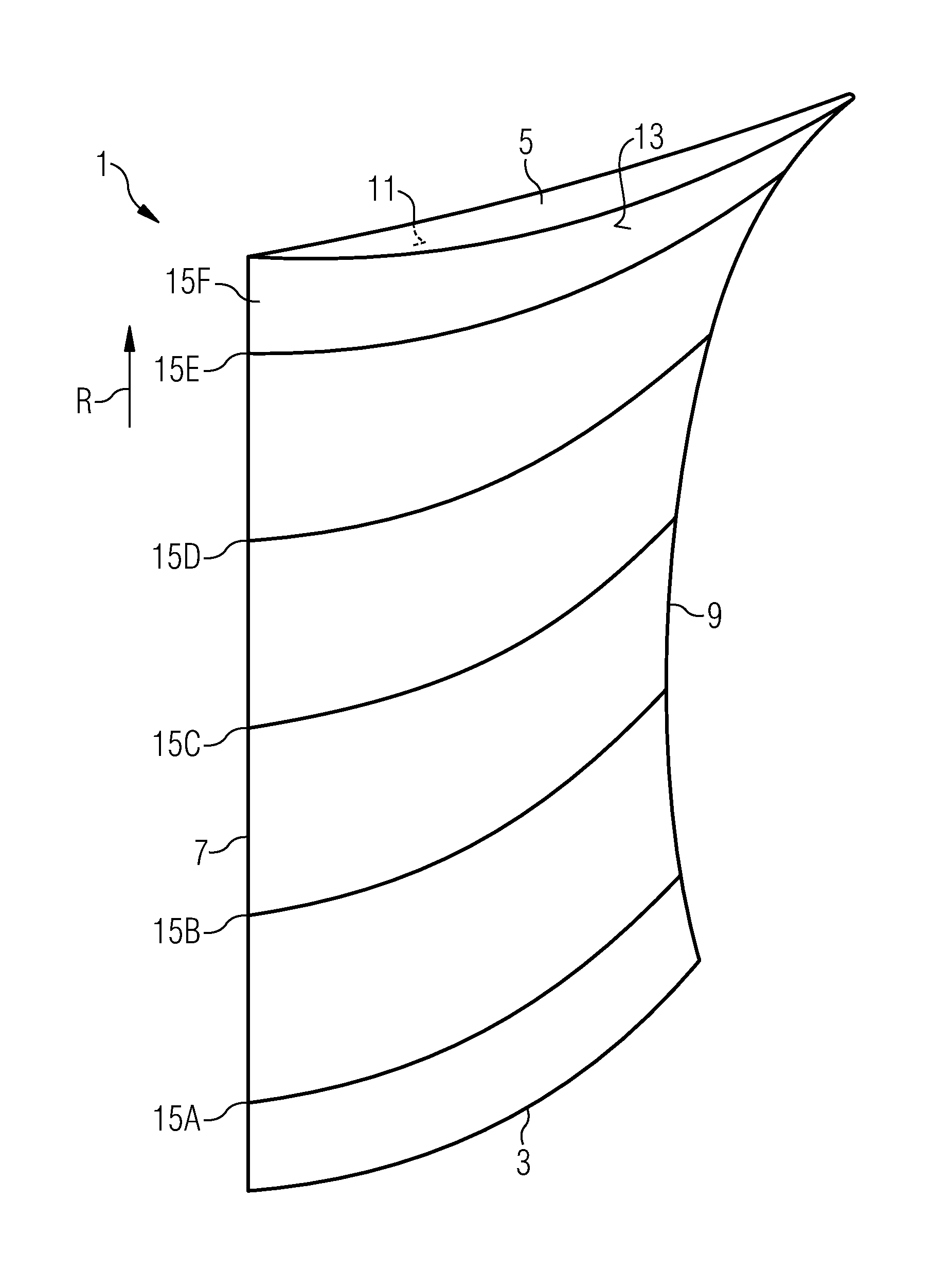
Figure 1 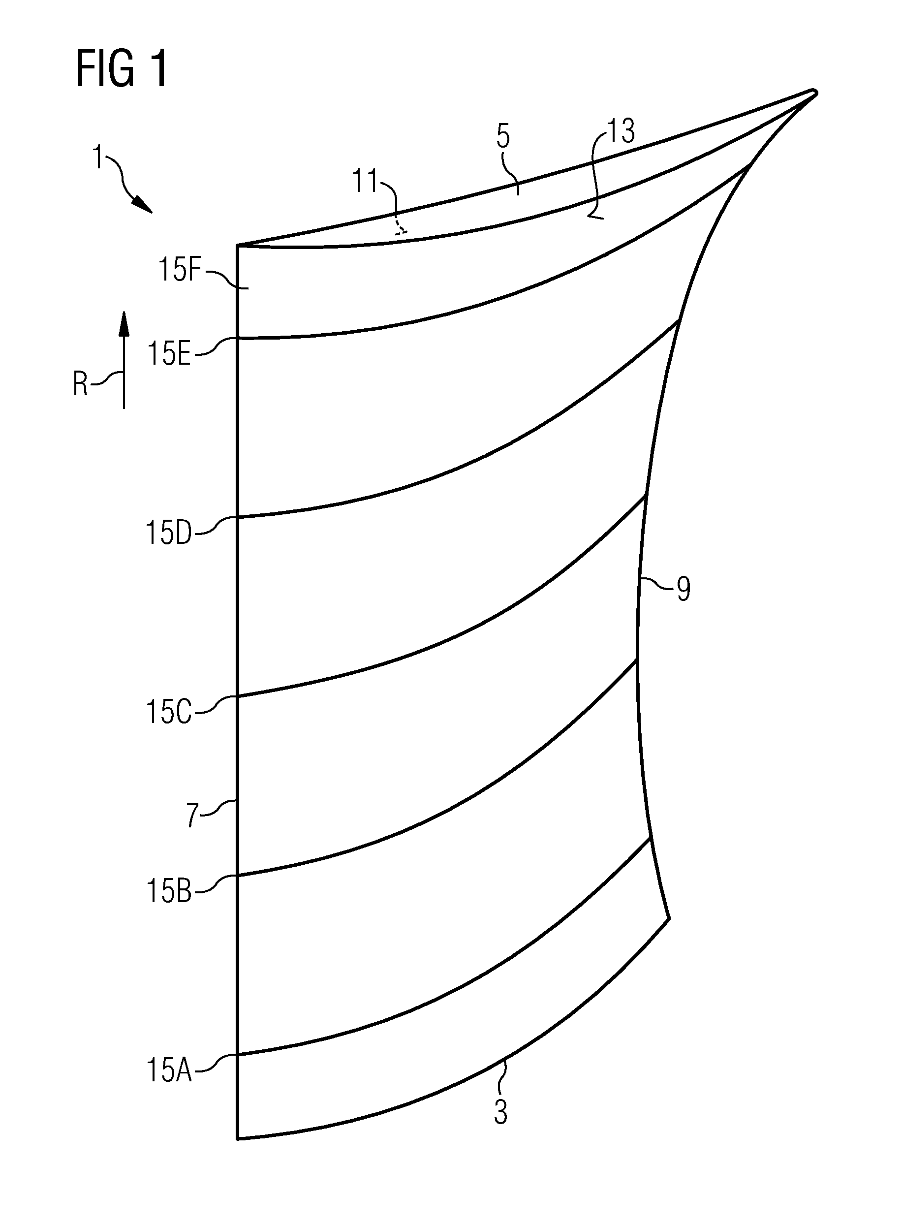
Figure 2 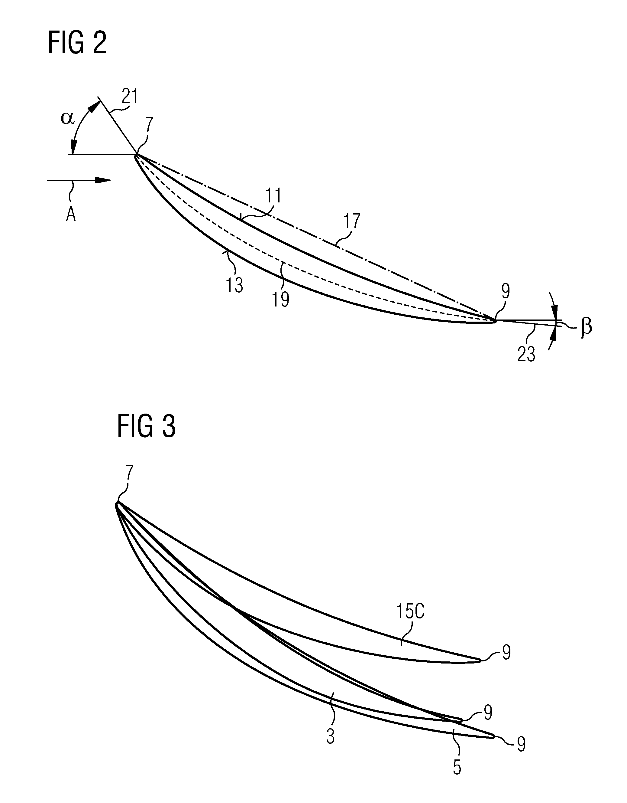
Figure 3
Abstract
Description
CROSS REFERENCE TO RELATED APPLICATIONS
[0001] This application is the US National Stage of International Application No. PCT / EP2009 / 054025, filed Apr. 3, 2009 and claims the benefit thereof. The International Application claims the benefits of European Patent Office application No. 08010816.0 EP filed Jun. 13, 2008. All of the applications are incorporated by reference herein in their entirety.FIELD OF INVENTION
[0002] The present invention relates to compressor vanes or blades for axial flow compressors and to an axial flow compressor.BACKGROUND OF INVENTION
[0003] Three-dimensional loss reduction and improving efficiency and stall margin of axial flow compressors are still technical issues in designing compressor blades and vanes. Three-dimensional losses limit the pressure rise capability of the compressor. Such losses result e.g. from flow separation in suction surface, endwall corners, leakage around the tip, and secondary flow regions. Optimising efficiency and stall margin always ...
Examples
Embodiment Construction
[0031]An airfoil using the features of the invention is shown in FIG. 1 in a three-dimensional view. The features noticeable in FIG. 1 can, in general, be used for the airfoils of compressor rotor blades as well as the airfoils of compressor stator vanes.
[0032]The airfoil 1 comprises a hub section 3 which shows towards the rotor when the airfoil is incorporated in a compressor, and a casing section 5 which shows towards the compressor casing when the airfoil 1 is incorporated into a compressor. It further comprises a leading edge 7 and a trailing edge 9 which both extend from the hub section 3 to the casing section 5. While the leading edge follows a straight line extending in radial direction R of the compressor the trailing edge 9 is curved with respect to the radial direction of the compressor. The trailing edge 9 may, in addition, be curved with respect to the axial direction of the compressor, too. Between the leading edge 7 and the trailing edge 9 extends a pressure surface 11...