
Brake disk
Patent Information
- Authority / Receiving Office
- US · United States
- Current Assignee / Owner
- Publication Date
- 2011-11-03
- Estimated Expiration
- Not applicable · inactive patent
Smart Images
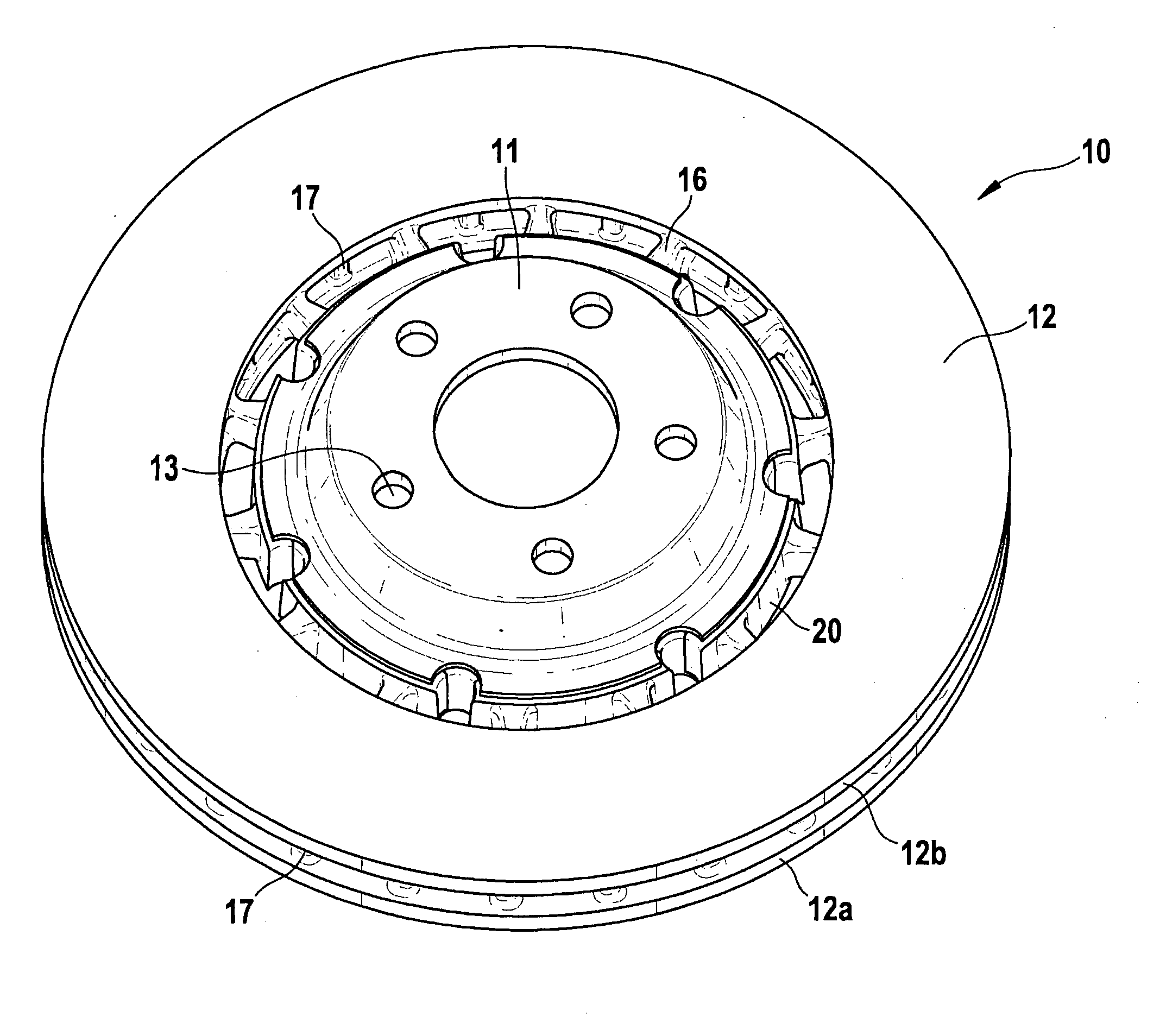
Figure 1 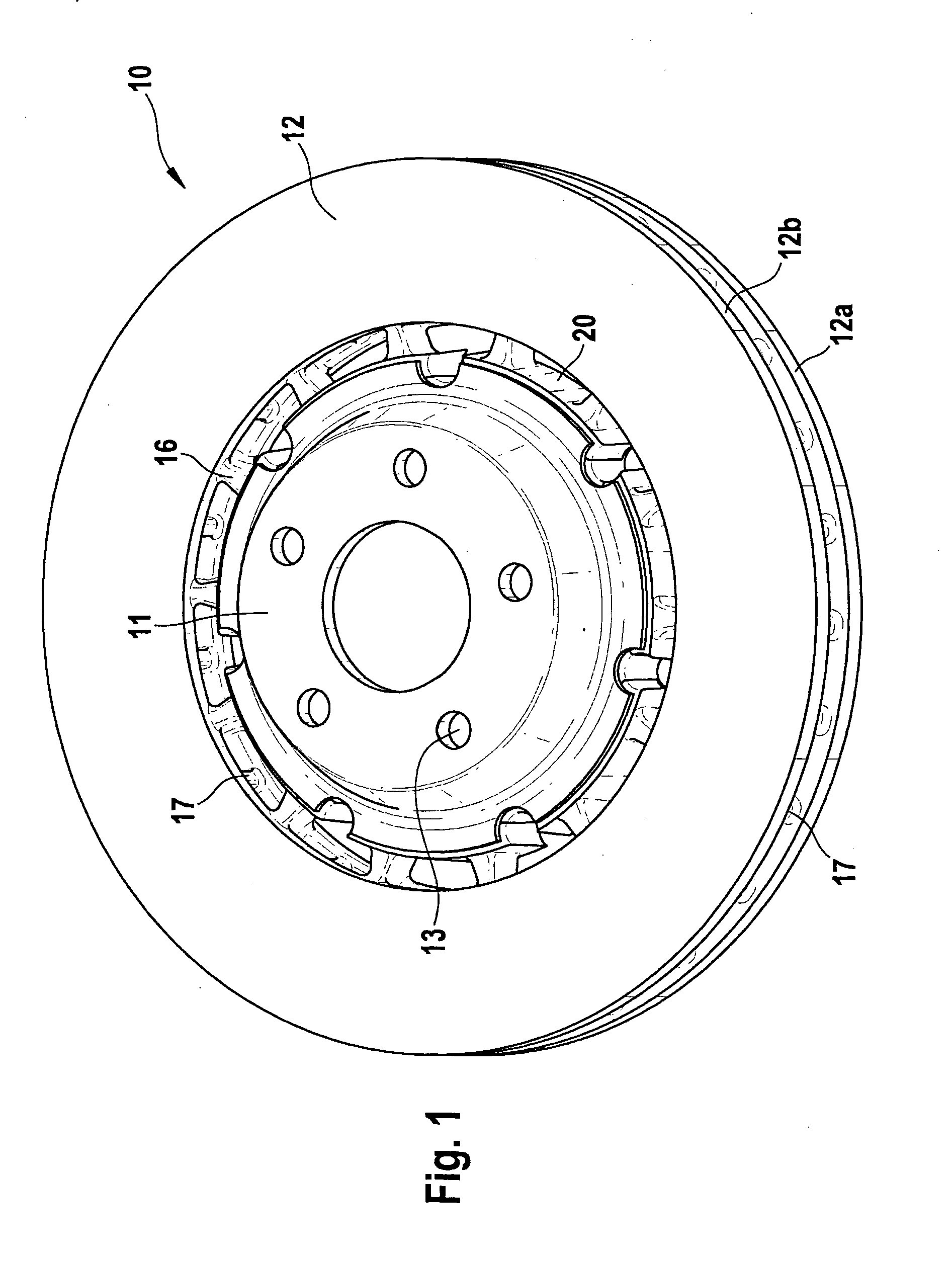
Figure 2 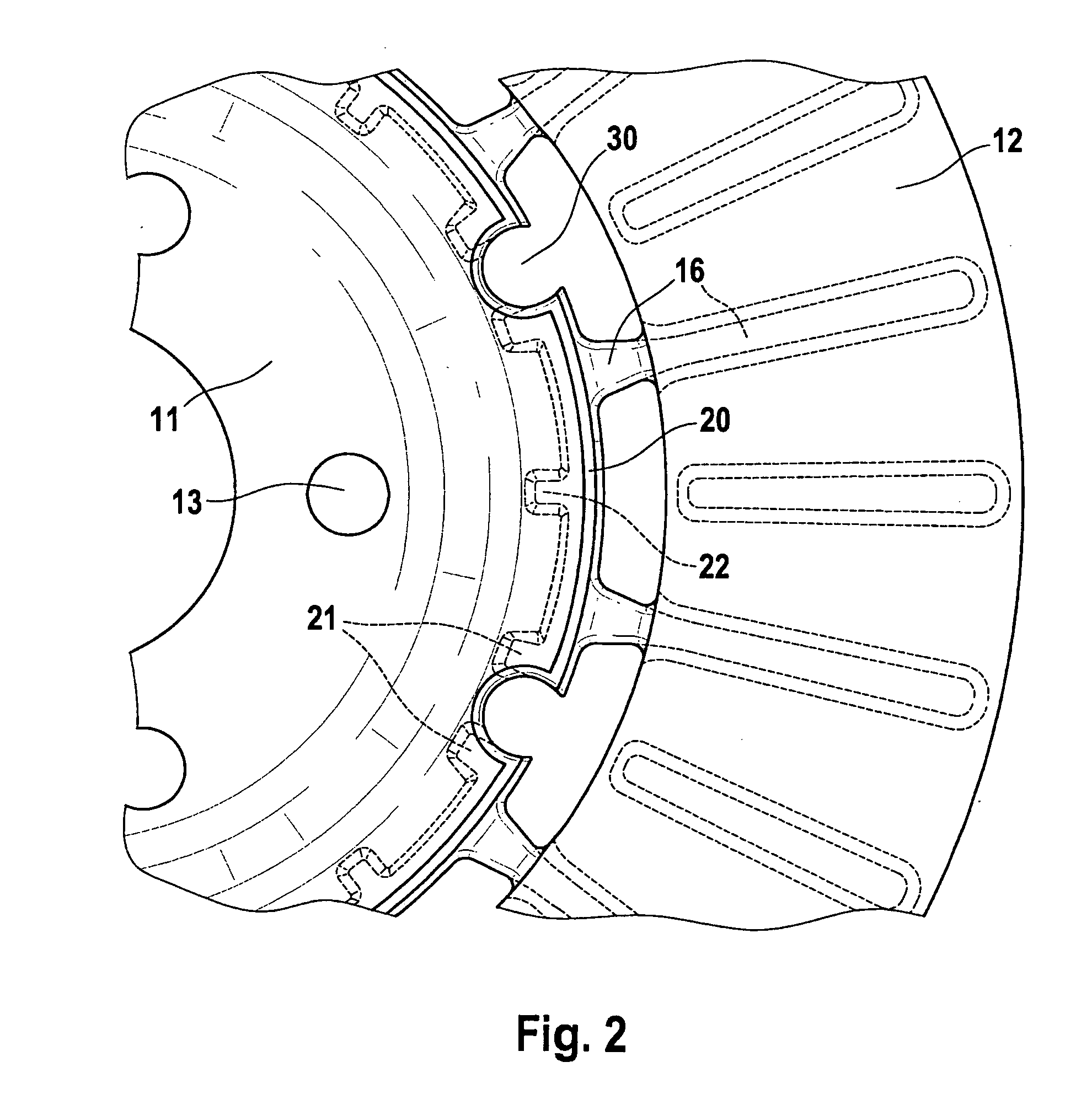
Figure 3
Abstract
Description
BACKGROUND OF THE INVENTION
[0001] 1. Field of the Invention
[0002] The present invention relates to a brake disk, e.g., a ventilated brake disk having a friction ring and a supporting structure connected to the friction ring via connecting links, e.g., a disk chamber.
[0003] 2. Description of Related Art
[0004] A ventilated brake disk is known from published German patent application document DE 43 32 951 A1, which has a friction ring and a supporting structure connected to the friction ring using connecting links. The connecting links are especially developed as pins, bolts or the like, and are positioned over the circumference of the supporting structure. The connecting links project into recesses in the circumferential wall of the friction ring. In the case of larger braking torques, there is a danger that, based on the free length of the connecting links, that is, based on the distance between supporting structure and friction ring, the connecting links, might bend and, in the extreme ...
Examples
Embodiment Construction
[0010]In FIG. 1, 10 designates a brake disk made up of a disk chamber 11 and a friction ring 12. A disk chamber 11 is fastened to a hub of a vehicle, in a manner not shown here, the screws for fastening it extending through boreholes 13 of disk chamber 11. Friction ring 12 is made up of two friction ring halves 12a and 12b, which are connected to each other by a plurality of crosspieces elements 17 that are distributed over the circumference and run particularly in the radial direction, so that a ventilated brake disk is created. Friction ring 12 is situated on disk chamber 11 with the aid of connecting elements 16 of a supporting ring 20 and extensions 21, 22. One integral component is represented by connecting elements 16, extensions 21, 22 and friction ring 12. This component is able to be produced in one operation. It is possible to produce the two friction ring halves 12a and 12b using the crosspieces 17 in one operation. In another operation, supporting ring 20 is produced hav...