
Canopy Of Working Vehicle
Patent Information
- Authority / Receiving Office
- US · United States
- Current Assignee / Owner
- Publication Date
- 2008-01-10
- Estimated Expiration
- Not applicable · inactive patent
Smart Images

Figure 1 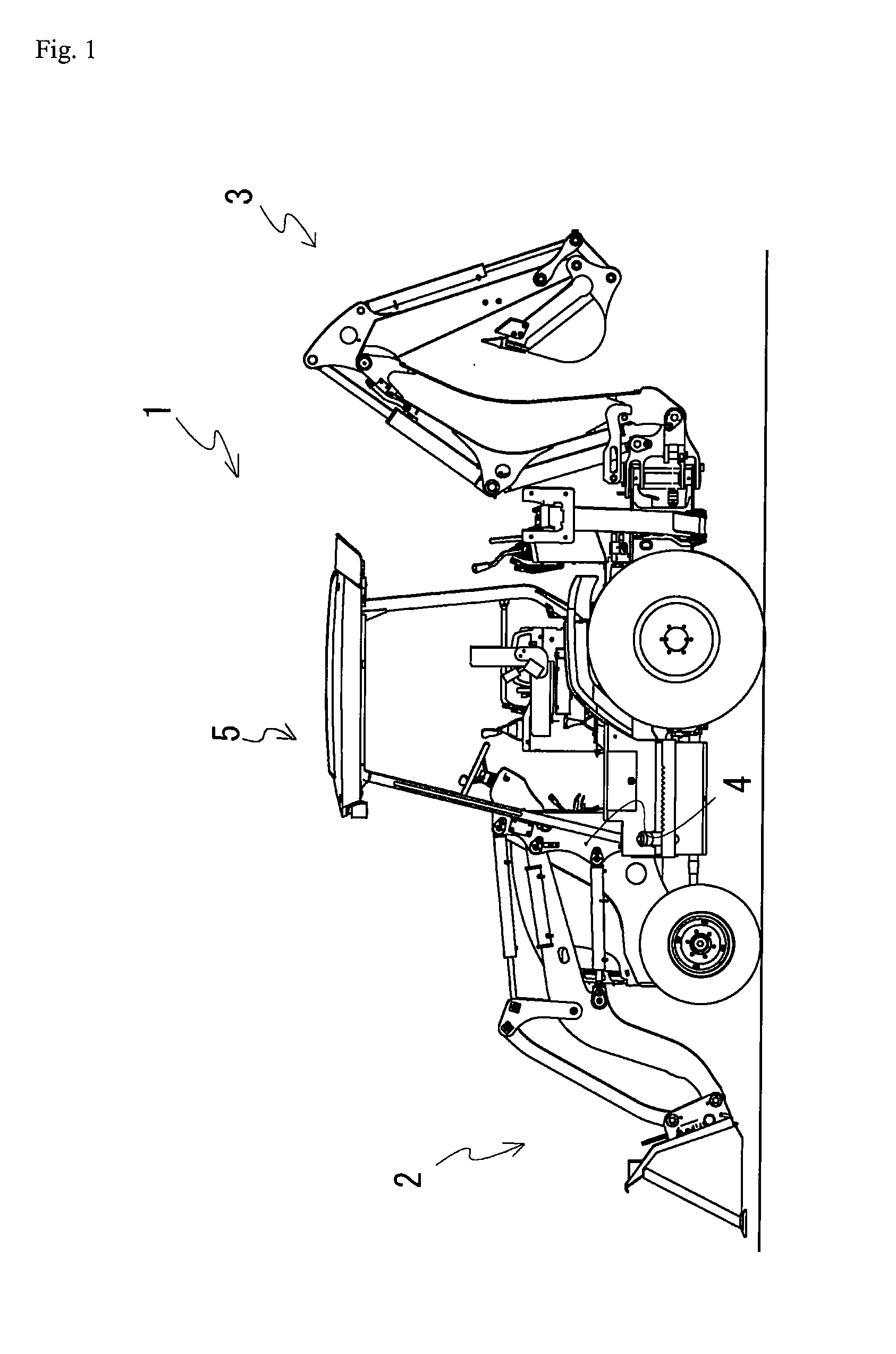
Figure 2 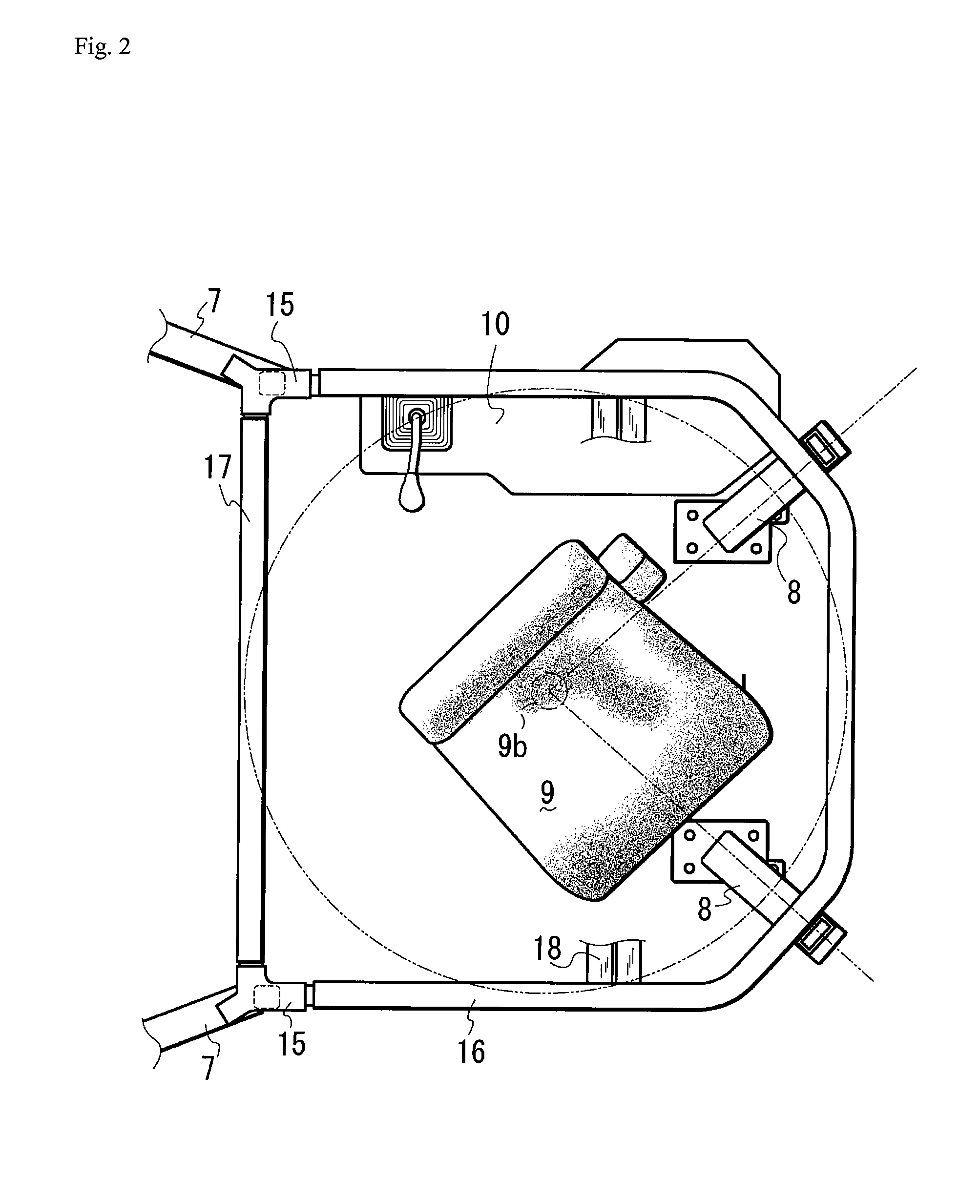
Figure 3
Abstract
Description
BACKGROUND OF THE INVENTION
[0001] 1. Field of the Invention
[0002] The present invention relates to a structure of a canopy arranged in a working vehicle, more specifically, to a frame structure of the canopy having, therein, a rotatable seat.
[0003] 2. Background Art
[0004] A work vehicle called Backhoe Loader is conventionally known in which a front loader is attached to the front part of the tractor vehicle body, and a backhoe is attached to the back part (see e.g., patent document 1). In the backhoe loader, the operator's seat is disposed in a freely forward and backward reverse rotatable manner on the tractor vehicle body by way of a reverse rotation support device, where the operator's seat faces the front when the tractor is traveling or when using the front loader and the operator's seat faces the back when using the backhoe by the reverse rotation support device. The reverse rotation device of the operator's seat is configured by parallel links and a turntable. ROPS (Roll ...
Examples
Embodiment Construction
[0036] An example of the present invention will now be described using the figures. FIG. 1 is a side view of the entire backhoe loader including a canopy. The work vehicle 1 is a backhoe loader, where the loader 2 serving as a loading device and a drilling device 3 are attached to the work vehicle 1. A bracket 4 is arranged on both left and right sides of the bonnet of the work vehicle 1, which bracket 4 is fixed to the vehicle body frame of the work vehicle 1. A canopy 5 is arranged on the vehicle body frame, and the operator operates the work vehicle in the canopy 5.
[0037] The structure of the frame configuring the canopy will now be described using FIGS. 2 to 4. FIG. 2 is a plan view showing the frame structure of the canopy, FIG. 3 is a side view of the same, FIG. 4 is a perspective view of the same, and FIG. 5 is a plan view showing the structure of the top frame. The canopy 5 is configured by front frames 7, 7, rear frames 8, 8, a top frame 16, and a front top frame 17. The f...