
Resin molding mold for intake manifold, intake manifold and method of resin molding for intake manifold
Patent Information
- Authority / Receiving Office
- US · United States
- Current Assignee / Owner
- Publication Date
- 2014-08-07
- Estimated Expiration
- Not applicable · inactive patent
Smart Images
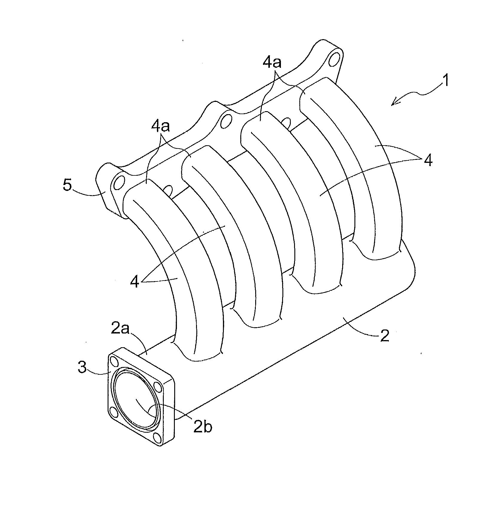
Figure 1 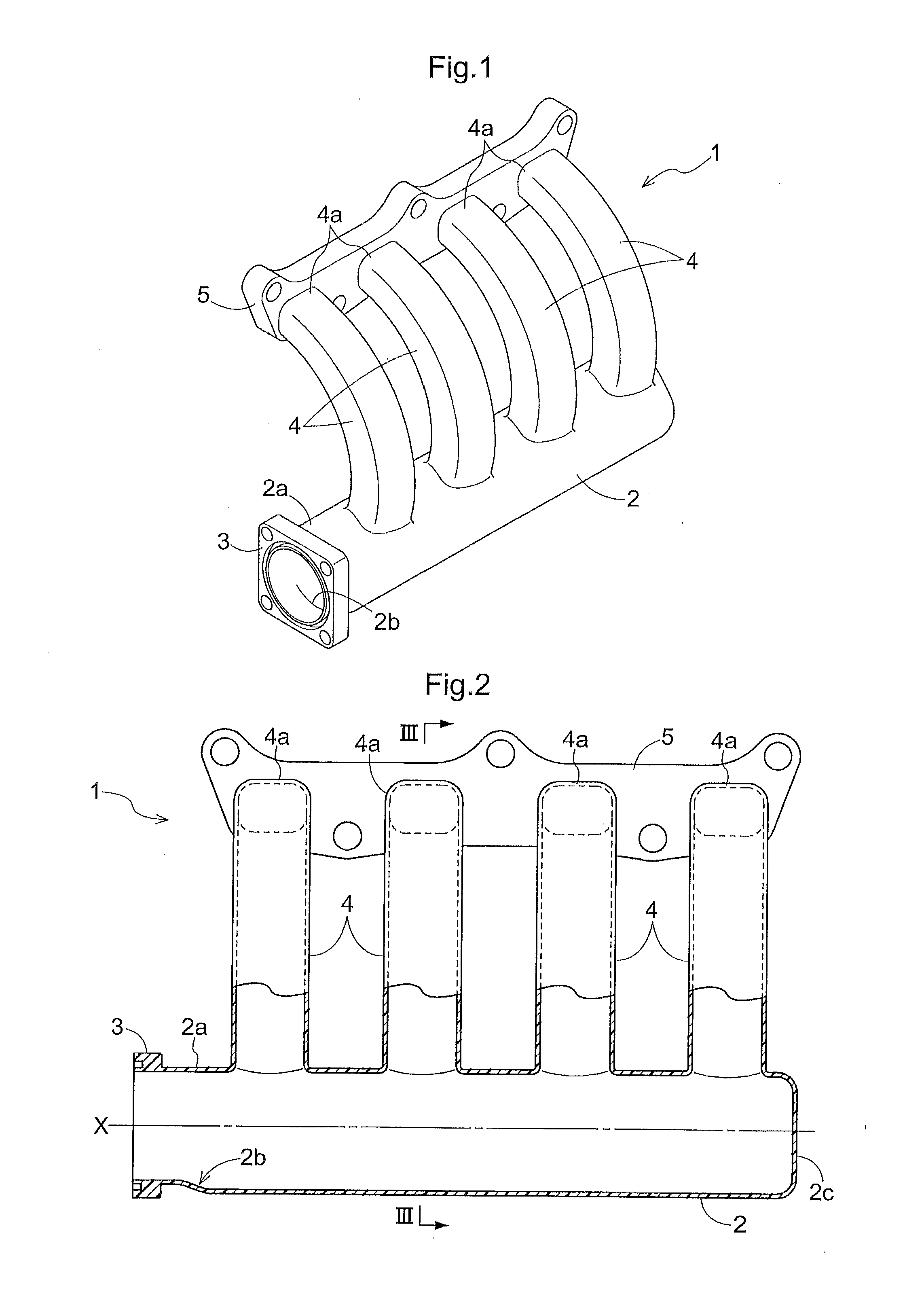
Figure 2 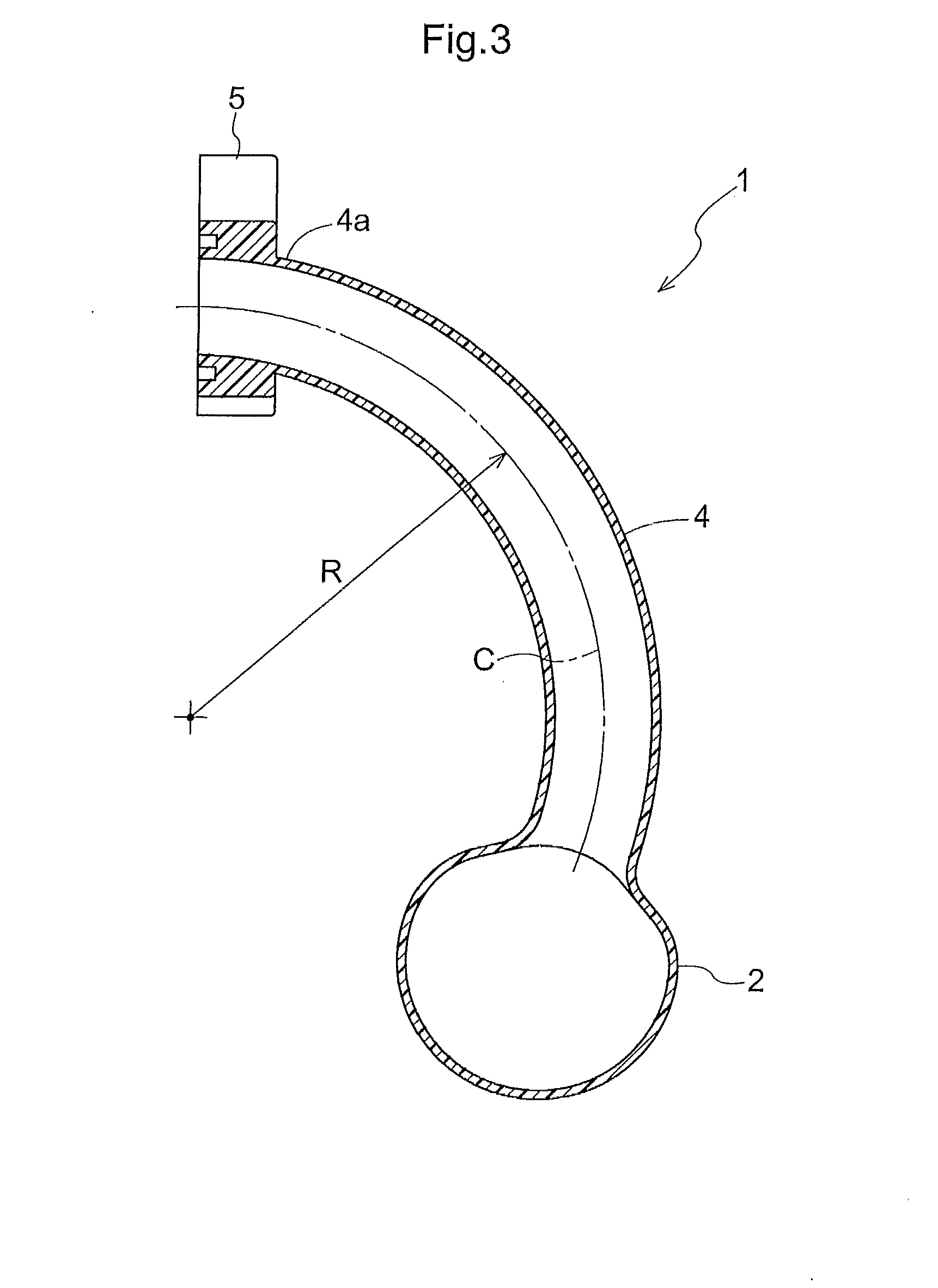
Figure 3
Abstract
Description
TECHNICAL FIELD
[0001] The present invention relates to a resin molding mold for an intake manifold made of a resin, an intake manifold obtained by the resin molding mold, and a method of resin molding for the intake manifold.BACKGROUND ART
[0002] In recent years, weight reduction and cost reduction for various automobile parts have been implemented by forming these parts of a resin. Regarding an intake manifold for use in an automobile too, resin products have been the mainstream. Many of such intake manifolds made of a resin are fabricated by the vibration welding method (see Patent Document 1) comprising forming a flange at a rim of each one of a plurality of split members and joining these respective flanges by vibration welding.
[0003] As other methods for molding an intake manifold formed of a resin, there are such methods as the lost core injection molding method according to which a core having a low melting point is inserted into a mold and then this core is discharged therefrom ...
Examples
second embodiment
[0067]As shown in FIGS. 9-11, a resin molding mold according to this embodiment includes four second core members 15 at positions in the outer circumference of the first core member 14. The second core members 15 include split molds 15A, 15B provided at positions in opposition to each other across the circumferential face of the first core member 14 in the longitudinal direction and having semi-circular cross section, and split molds 15C, 15D provided at positions adjacent the split molds 15A, 15B and having arcuate cross section.
[0068]In the case of the resin molding mold of this embodiment, after resin molding, of the tank core mold 12, the first core member 14 disposed at the center is extracted through the opening (inward space) V2 of the throttle-side flange 3, in advance of the other core member 15 by a relative movement of the first core member 14 along the direction of the axis X. Thereafter, of the second core members 15, the slit molds 15C, 15D are moved temporarily into t...