
Apparatus and process for the surface treatment of carbon fibers
a technology of carbon fiber and surface treatment, which is applied in the direction of weaving, transportation and packaging, coatings, etc., can solve the problems of circumventing many of the costly and environmentally harmful shortcomings inherent in electrochemical treatment methods, and achieves the effects of improving the adhesion of fibers, increasing surface atomic oxygen content, and increasing the level of surface functional groups
Patent Information
- Authority / Receiving Office
- US · United States
- Patent Type
- Applications(United States)
- Current Assignee / Owner
- Publication Date
- 2014-08-07
Smart Images
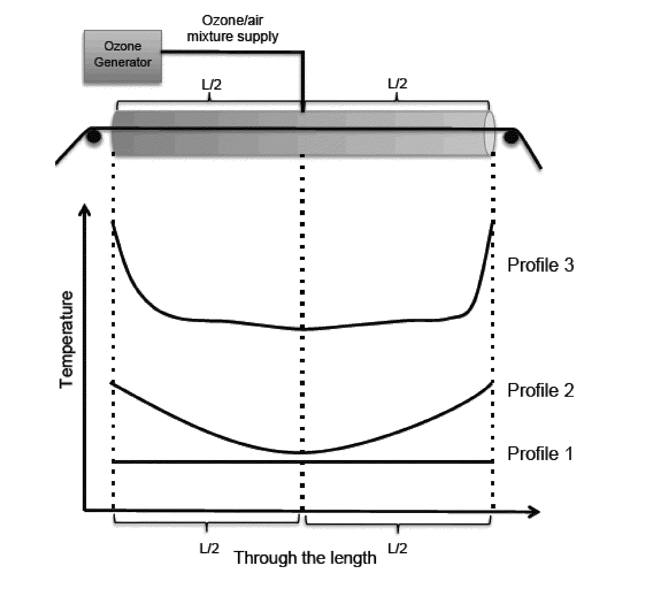
Figure 1 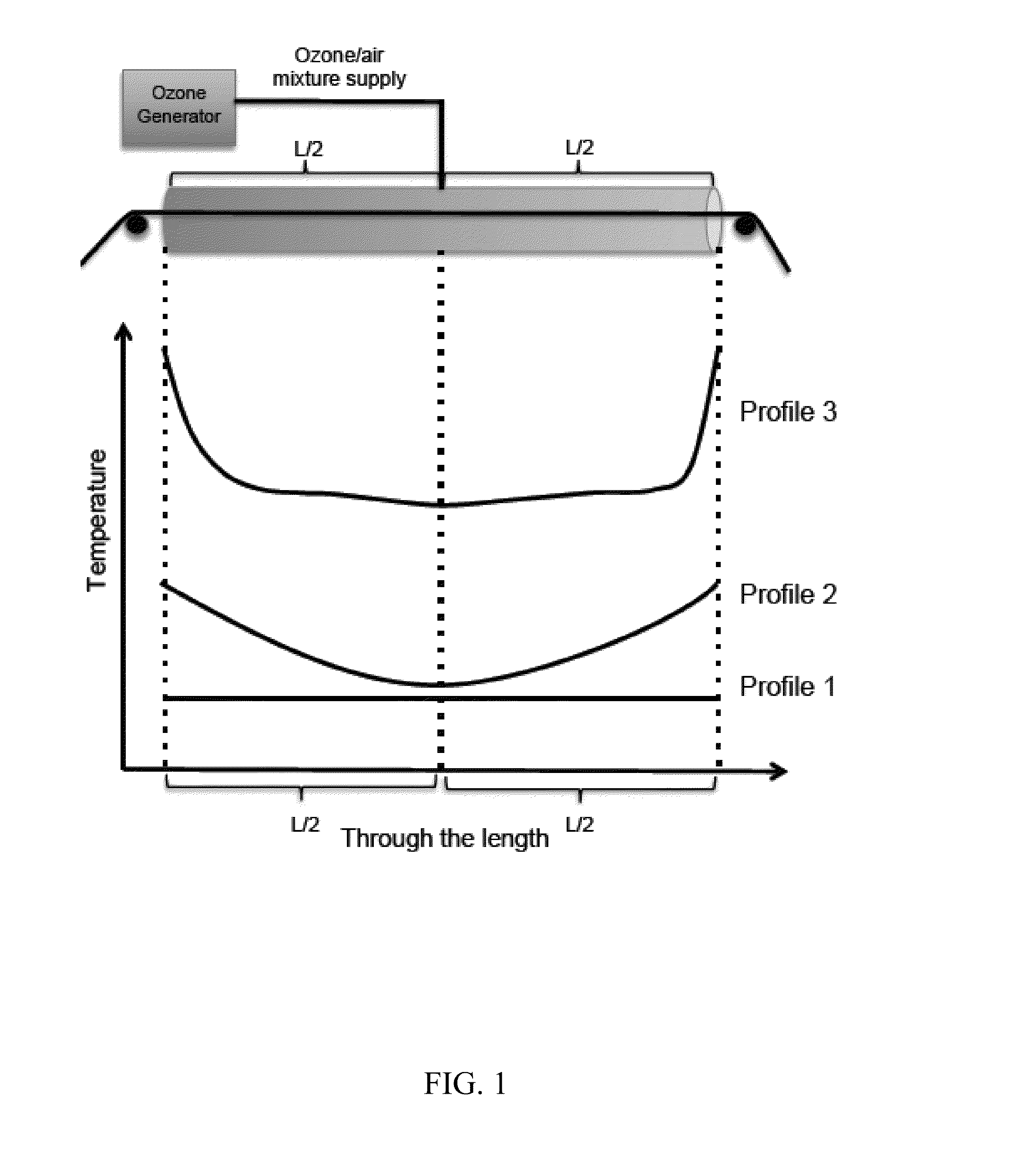
Figure 2 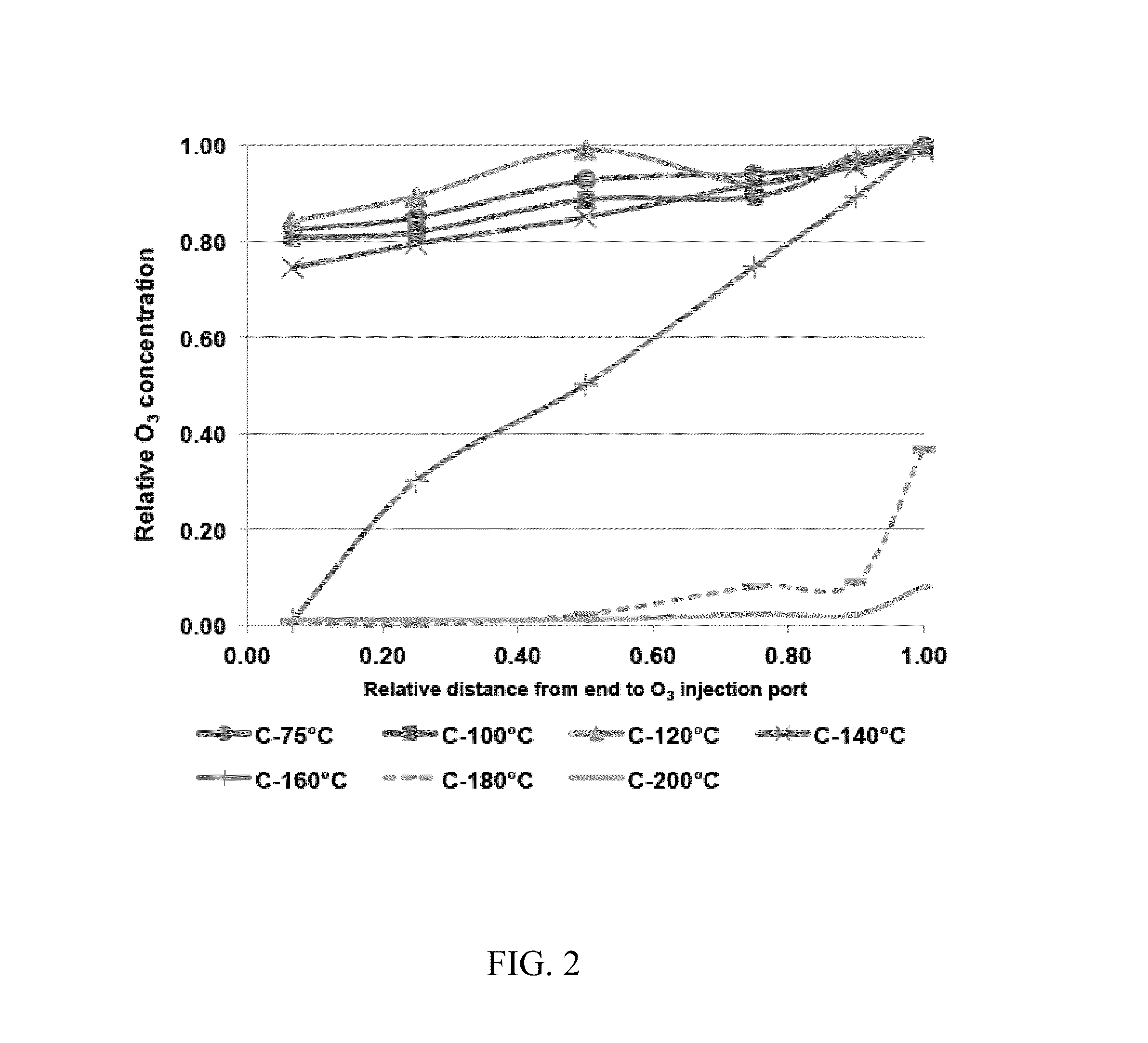
Figure 3
Abstract
Description
CROSS REFERENCE TO RELATED APPLICATIONS
[0001] This application is a divisional of U.S. application Ser. No. 13 / 363,711 filed on Feb. 1, 2012, the contents of which are incorporated herein by reference in their entirety.
[0002] This invention was made with government support under Prime Contract No. DE-AC05-000R22725 awarded by the U.S. Department of Energy. The government has certain rights in the invention.FIELD OF THE INVENTION
[0003] The present invention relates, generally, to the manufacture and surface treatment of carbon fibers, and their composite materials.BACKGROUND OF THE INVENTION
[0004] Carbon fiber reinforced polymer composites are known for their outstanding mechanical properties with a low density. Some of their outstanding mechanical properties include superior shear properties and impact resistance. For this reason, they have been of interest to many fields, particularly for rugged applications, such as the space and aeronautics industries, military equipment, transportat...
Examples
example 1
Processing of Carbon Fiber
Experiment A
[0069]In this experiment, the carbon fiber was in the form of a 50,000 filament tow. Carbon fibers were drawn continuously through a heated Pyrex® glass circular tubular reactor having an internal diameter (ID) of 1.5 inches (1.5″) and a length of 60 inches (total reactor volume of 105.98 cubic inches). Approximately 9 wt % ozone gas was supplied from the middle top of the tube. The residence time for the carbon fiber in the reactor was about 90 seconds. The flow rate of the carrier gas was set at 2 lt / min (122.04 cubic inches / min). Thus, the approximate reactor renewal time was 0.868 minutes. A general schematic of the apparatus and process is shown in FIG. 1.
[0070]Using the above system, ozone decomposition kinetics and distribution were analyzed by varying the processing temperature. FIG. 2 is a chart plotting observed relative ozone concentration to relative distance from the ozone injection port. A relative distance of 1.00 is taken as the ...
experiment b
[0071]The dimensions of the reactor and materials used in the reactor also have a significant effect on the kinetics and distribution of ozone decomposition. This example employed a metal 5″ by 5″ reactor in the tubular reactor of 60″ length as fibers moved through the center portion of the reactor. Ozone and air densities were 2.14 kg / m3 and 1.29 kg / m3, respectively. Due to the heavy nature of ozone molecules, they tend to accumulate at the bottom of the reactor. Although the proper balance of ozone decomposition may be achieved, the generated active species may not react with the carbon fiber effectively if most of the reaction is occurring below the area where the fibers move. This results in poor surface treatment.
[0072]Regarding the dimensions of the reactor, a reduced interaction between carbon fiber surfaces and ozone was observed in larger diameter tubes, particularly those having a diameter greater than three inches. More optimal results were observed using a circular glass...
experiment c
[0073]In this experiment, carbon fiber was in the form of a 50,000 filament tow. Carbon fibers were drawn continuously through a heated Pyrex® glass circular tubular reactor having an internal diameter (ID) of 3 inches (3″) and a length of 120 inches. Approximately 7 wt % ozone gas was supplied from both the bottom and the top every 24″ along the length of the reactor (8 individual ozone supply injection ports). The residence time for the carbon fiber in the reactor was about 90 seconds. The overall flow rate of the carrier gas was set at 10 lt / min, distributed equally among the 8 injection ports. This equated to a reactor renewal rate of 1.39 minutes. A uniform 160° C. temperature profile was maintained during the experiment. The apparatus and process is similar to that depicted in FIG. 1, except where indicated.
[0074]The atomic composition of the surface of the processed fibers, as measured by XPS, is shown in Table 1 below:
TABLE 1Atomic composition of the surface of processed car...