
Method and apparatus for measuring a part
a technology for measuring parts and parts, applied in the direction of process and machine control, program control, instruments, etc., can solve the problems of significant inaccuracy in the measurement of parts, inability to separate 1sup>, and inability to measure the part accurately, so as to reduce the uncertainty of measurement and avoid systematic errors due to a single measurement direction of the prob
Patent Information
- Authority / Receiving Office
- US · United States
- Current Assignee / Owner
- Publication Date
- 2015-12-31
Smart Images
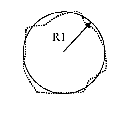
Figure 1 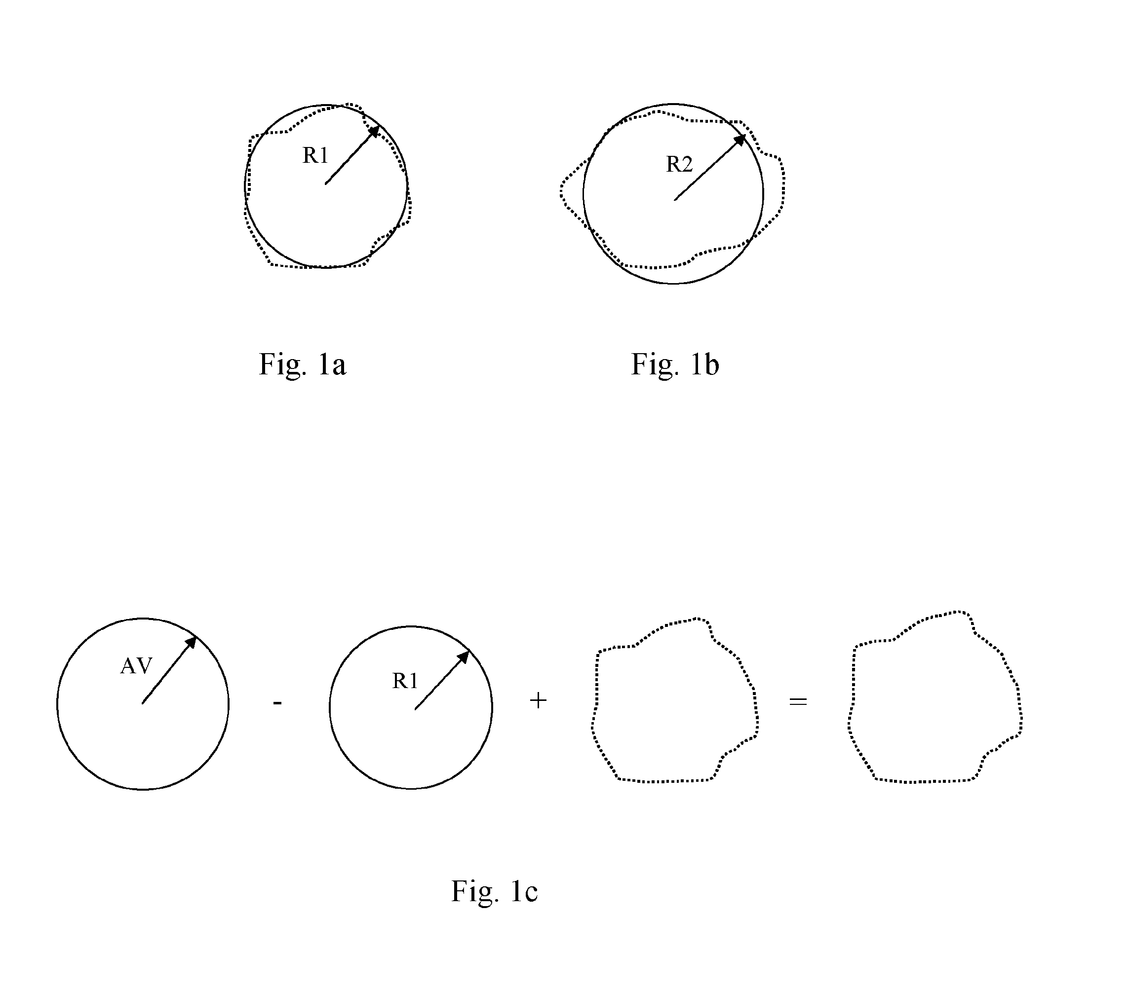
Figure 2 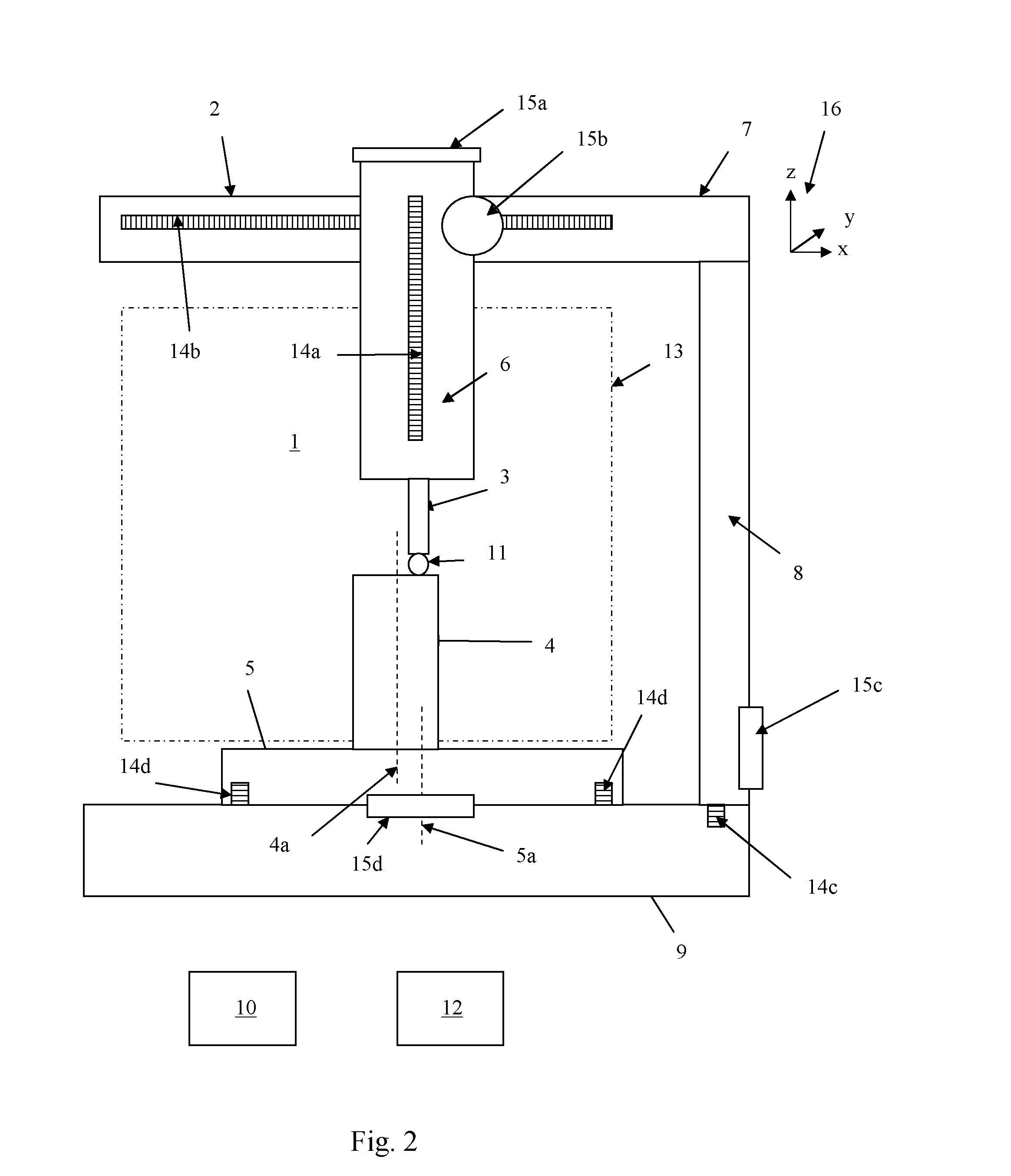
Figure 3
Abstract
Description
FIELD OF INVENTION
[0001] This invention concerns a method and apparatus for measuring a part. This invention has particular application to measuring a part using a coordinate positioning machine, such as a machine tool or coordinate measuring machine.BACKGROUND
[0002] In machine tools, it is known to measure a part using a contact probe by moving a contact probe along a path such that the probe contacts a surface of the part at a number of points on the surface. A location of the points of contact can be determined from signals from the machine tool and contact probe and an appropriate shape fitted to these points to obtain a representation of the surface. It is also known to rotate the part with the contact probe fixed in position. Examples of these methods are described in U.S. Pat. No. 3,866,829.
[0003] In U.S. Pat. No. 3,866,829, the contact probe is movable parallel to the rotational axis to take measurements at different heights on the part. However, it is also known to move the co...
Examples
Embodiment Construction
[0056]Referring to FIG. 2, a coordinate positioning machine 1 comprises a machine tool 2 and a contact probe 3, in this embodiment a multi-axis contact probe, mounted on the machine tool 2 for measuring a part 4. The machine tool comprises a rotary table 5 on which the part 4 can be mounted. The rotary table 5 comprises a rotary axis 5a The contact probe 3 is mounted to a quill 6 which is mounted on arms 7 and 8 such that the contact probe 3 can be moved in three linear directions, x, y and z relative to a base 9. The extent of movement of the probe 3 will be constrained by the construction of the machine tool 2 and may not extend across the entire volume of a part mounted in the machine tool 2. In this embodiment, the volume within which the probe 3 can move is indicated by dotted and dashed box 13.
[0057]Motors 15a, 15b, 15c, 15d move the rotary table 5, quill 6 and arms 7 and 8 under the control of controller 10, such as processor programmed with suitable software. Encoders 14a, 1...