
Brake control device
Patent Information
- Authority / Receiving Office
- US · United States
- Current Assignee / Owner
- Publication Date
- 2017-02-09
Smart Images

Figure 1 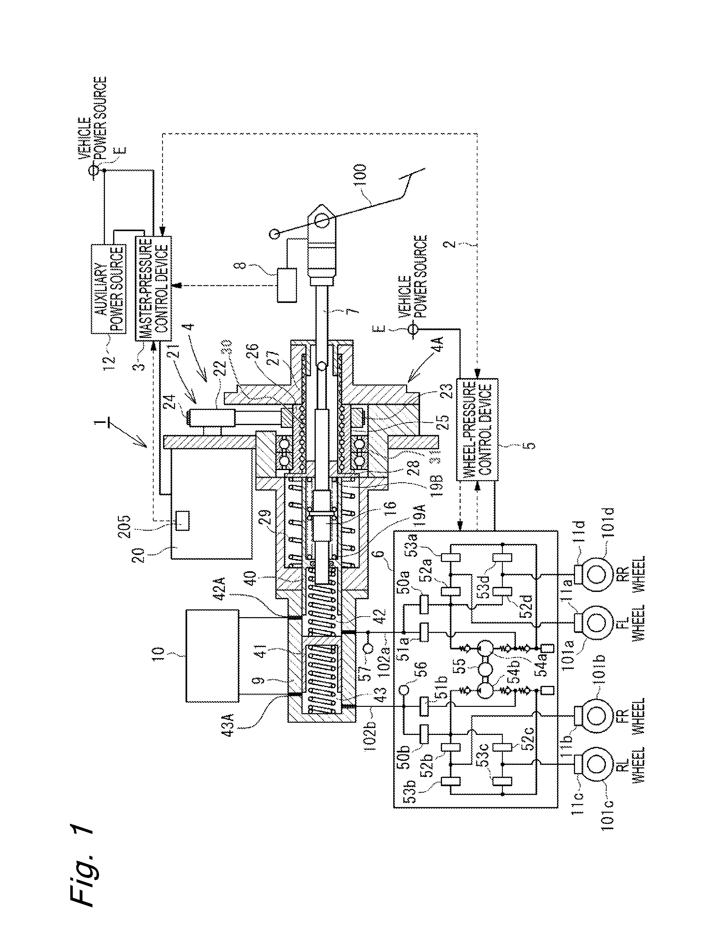
Figure 2 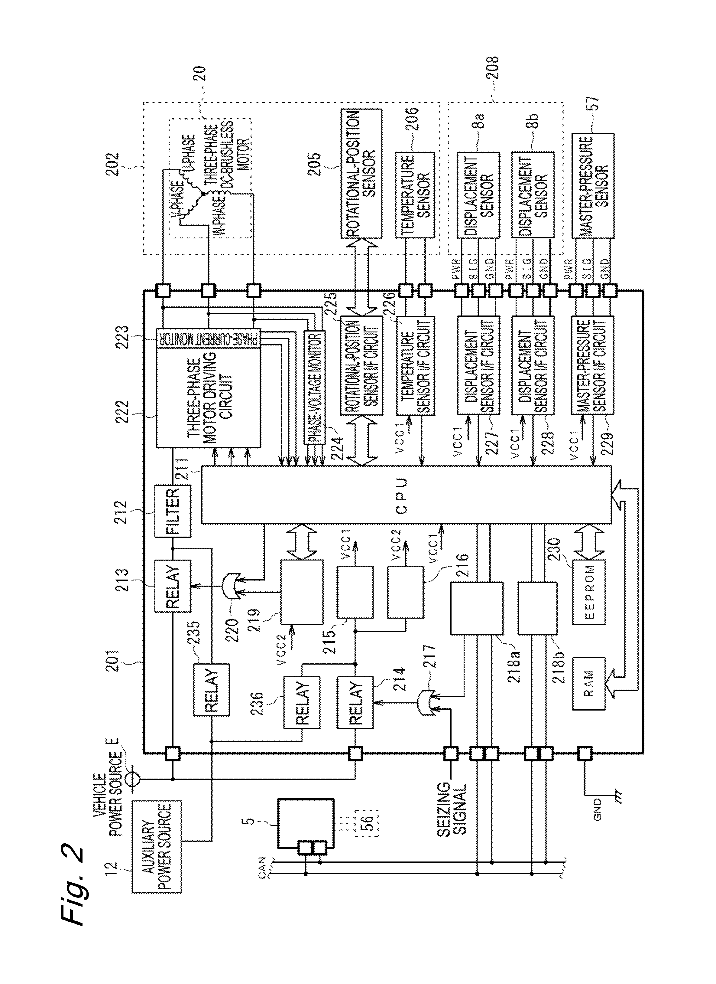
Figure 3
Abstract
Description
CROSS-REFERENCE TO RELATED APPLICATIONS
[0001] This is a continuation-in-part application of a U.S. patent application Ser. No. 13 / 626,345, filed Sep. 25, 2012, which is incorporated by reference herein in its entirety and to which priority is claimed.BACKGROUND OF THE INVENTION
[0002] 1. Technical Field
[0003] The present invention relates to a brake control device which is actuated by using an electric motor as a driving source.
[0004] 2. Description of the Related Art
[0005] For example, as described in International Publication No. WO2010 / 113574, as a brake control device for an automobile, there is a brake control device for generating a servo force by using an electric motor as a driving source in accordance with an operation of a brake pedal, which is performed by a driver, to perform braking.
[0006] It is desired that the brake control device for an automobile can be actuated even when an ignition switch is in an OFF state. Therefore, in the electric brake control device described above...
Examples
first embodiment
[0079]The first embodiment is described referring mainly to FIG. 5.
[0080]In the first embodiment, when the system end conditions are satisfied, the power-supply interruption control is executed to interrupt the vehicle power source E and supply the necessary electric power from the auxiliary power source 12. In this manner, the power-supply interruption control is continued by the master-pressure control device 3 until the electric power stored in the auxiliary power source 12 is depleted.
[0081]An example of a control flow for executing the power-supply interruption control according to this embodiment is illustrated in FIG. 5. Referring to FIG. 5, in Steps S50 to S53, the same processing as that performed in Steps S11 to S14 illustrated in FIG. 3 is performed. Then, when it is determined in Step 51 that the vehicle power source E does not fail, that is, when it is determined that the vehicle power source E is normal and the electric power is supplied from the vehicle electric power...
second embodiment
[0085]In the second embodiment, when the system end conditions are satisfied, the power-supply interruption control is executed to interrupt the vehicle power source E and supply the necessary electric power from the auxiliary power source 12 to the CPU 211 and the monitoring control circuit 219 when the amount of electric power (amount of charge) of the auxiliary power source 12 is equal to or larger than a given amount, so as to reduce the electric power consumption. Further, when the operation of the brake pedal 100, the operation of the master-pressure control device 3 is made possible immediately.
[0086]An example of a control flow for executing the power-supply interruption control according to this embodiment is illustrated in FIG. 6. Referring to FIG. 6, in Step S64 corresponding to Step S54 of the first embodiment, when the system end conditions have been satisfied, the power source is switched from the vehicle power source E to the auxiliary power source 12 in Step S65 so a...
third embodiment
[0088]In the third embodiment, when the system end conditions are satisfied, the power-supply interruption control is executed to interrupt the vehicle power source E and supply the necessary electric power from the auxiliary power source 12 to the CPU 211 and the monitoring control circuit 219. In this manner, the electric power consumption is reduced for a predetermined period of time and, when the operation of the brake pedal 100 is detected, the master-pressure control device 3 can operate immediately.
[0089]An example of a control flow for executing the power-supply interruption control according to this embodiment is illustrated in FIG. 7. Referring to FIG. 7, in Step S74 corresponding to Step S54 in the first embodiment, when the system end conditions have been satisfied, the power source is switched from the vehicle power source E to the auxiliary power source 12 in Step S75. In Step S76, it is determined whether or not a predetermined period of time has elapsed after the con...