
Control device for automatic transmission of vehicle and control method for automatic transmission of vehicle
a technology of control device and automatic transmission, which is applied in mechanical equipment, transportation and packaging, and gearing, etc., can solve the problems of possible deformation of startability of the vehicle, impact shock degradation of the durability of the friction engagement device, so as to reduce increase the rotation resistance of the input shaft, and reduce the effect of the rotational speed of the input sha
Patent Information
- Authority / Receiving Office
- US · United States
- Patent Type
- Applications(United States)
- Current Assignee / Owner
- Publication Date
- 2017-03-02
Smart Images
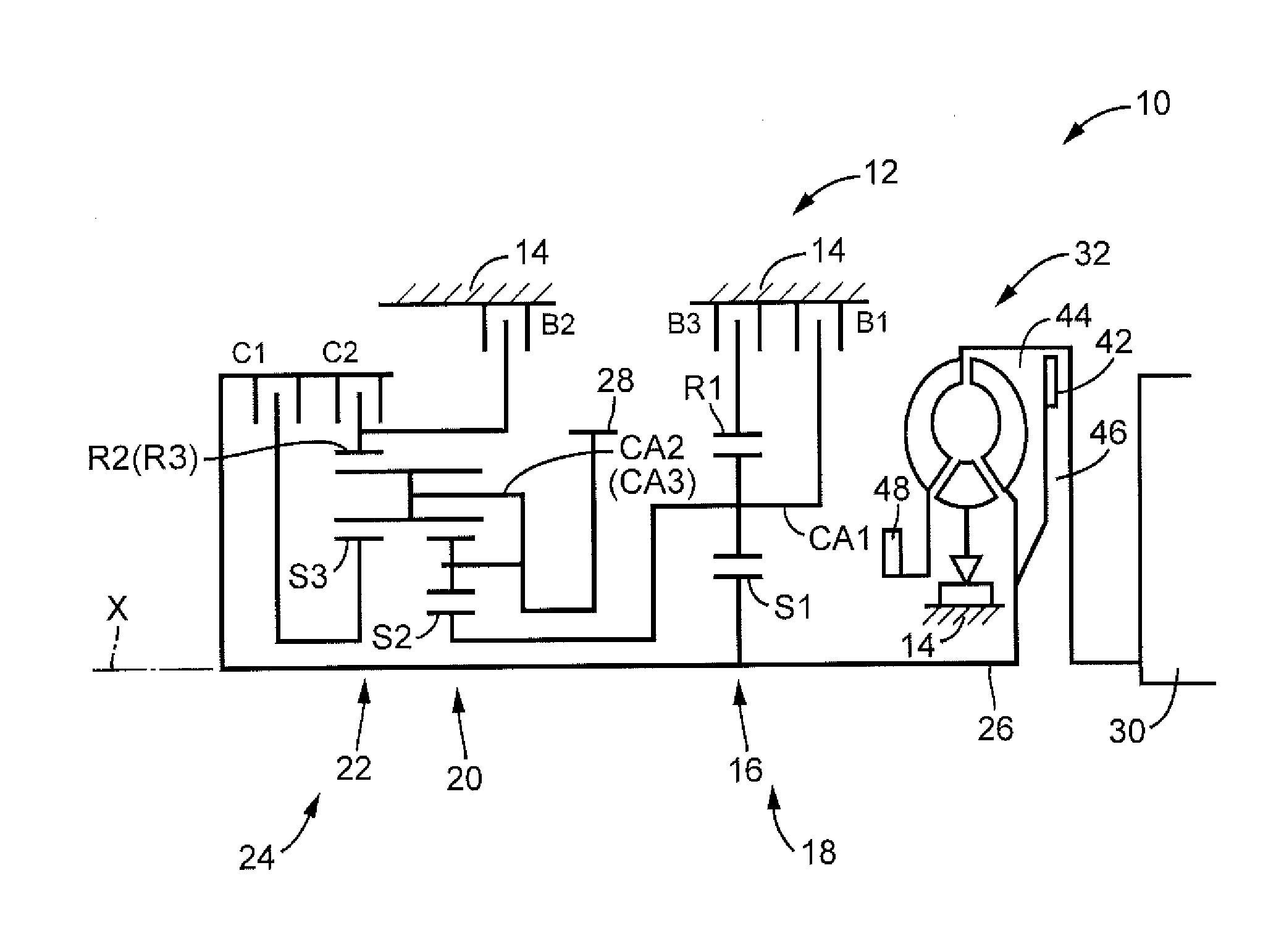
Figure 1 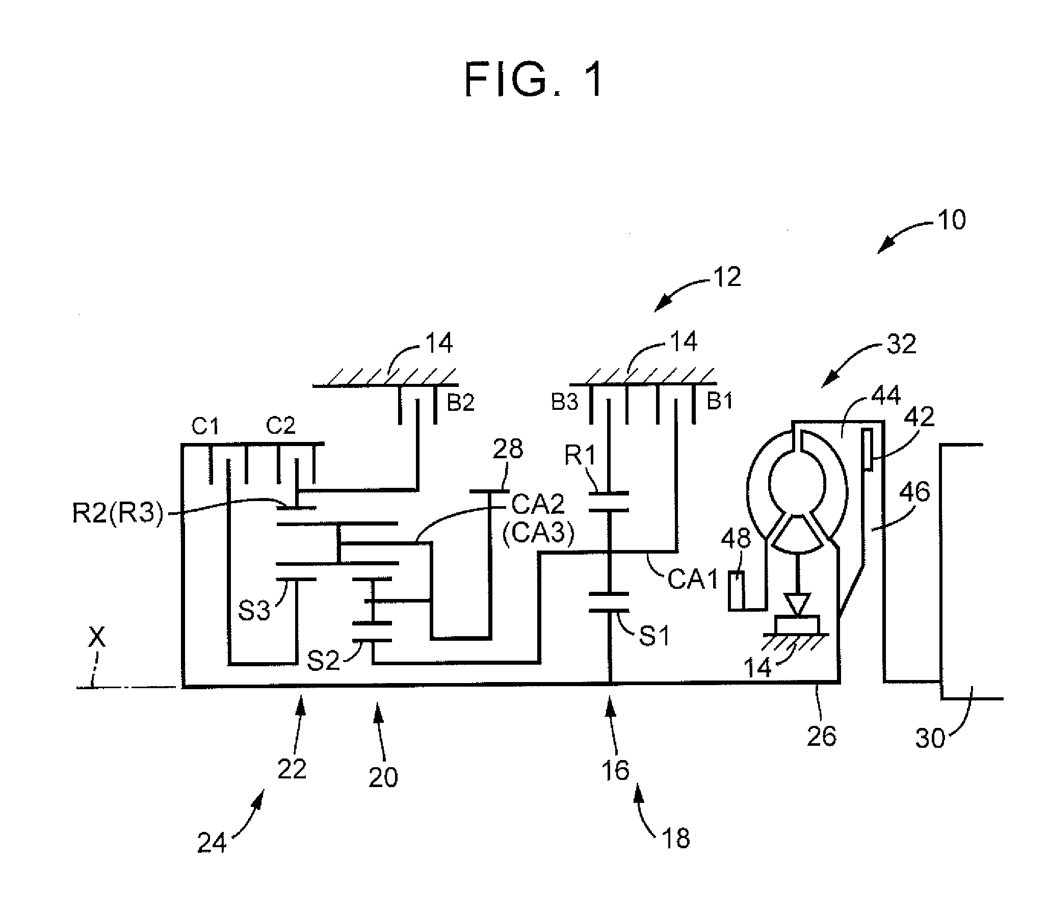
Figure 2 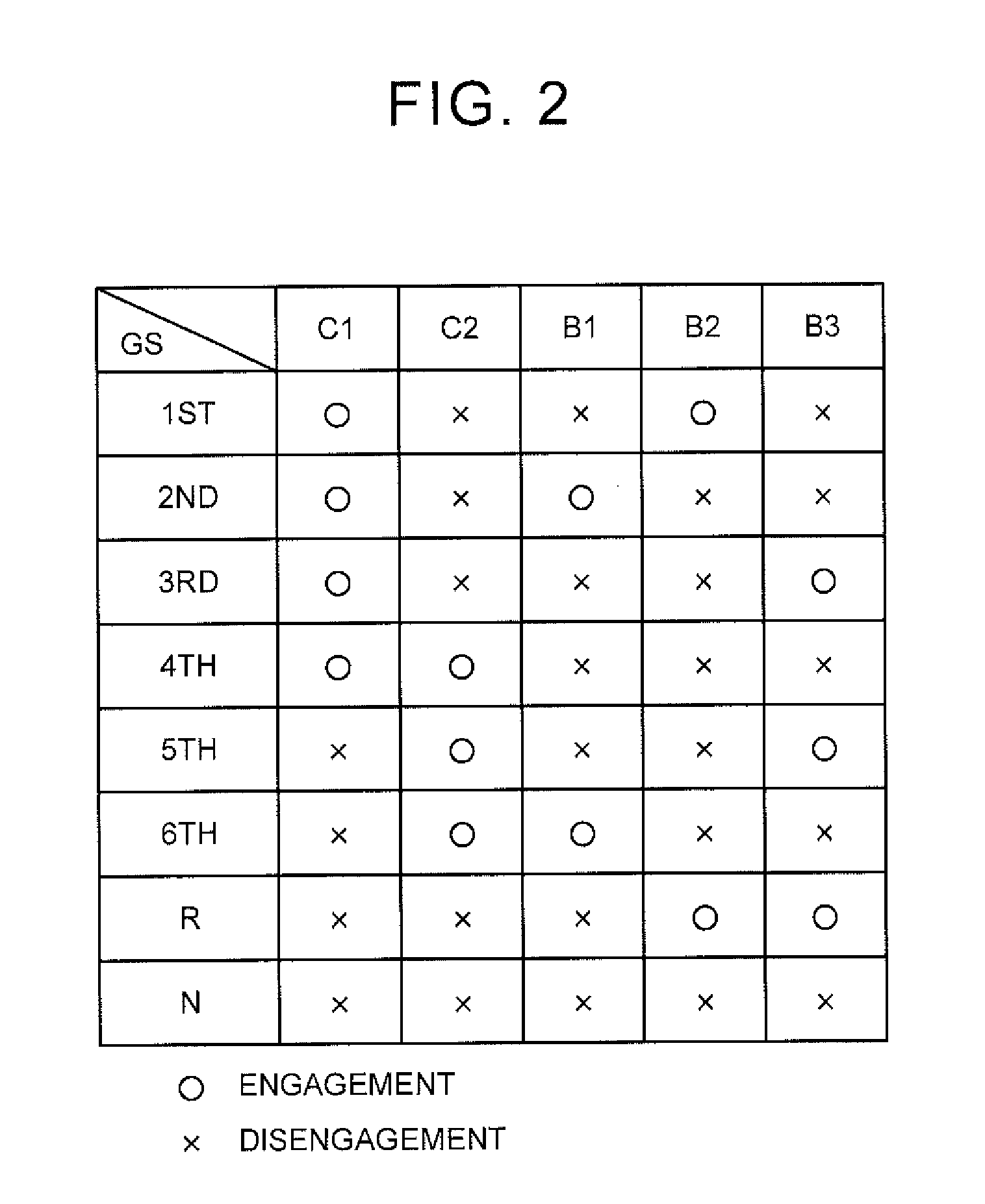
Figure 3
Abstract
Description
INCORPORATION BY REFERENCE
[0001] The disclosure of Japanese Patent Application No. 2015-169792 filed on Aug. 28, 2015 including the specification, drawings and abstract is incorporated herein by reference in its entirety.BACKGROUND
[0002] 1. Technical Field
[0003] The present disclosure relates to a control device and a control method for an automatic transmission of a vehicle.
[0004] 2. Description of Related Art
[0005] When an engine of a vehicle that includes an automatic transmission is restarted after being stopped, there is a case where an accelerator pedal is depressed when the transmission is in a neutral state. This causes generation of an engagement shock and degradation in durability of a friction engagement device. Japanese Patent Application Publication No. 11-351001 (JP 11-351001 A) discloses control of the friction engagement device for purposes of reducing the engagement shock and suppressing the degradation in the durability of the friction engagement device. More specifical...
Examples
Embodiment Construction
[0023]A detailed description will hereinafter be made on an embodiment with reference to the drawings.
[0024]FIG. 1 is a skeletal view for explaining a schematic configuration of an automatic transmission 12 that is provided in a vehicle 10 according to the embodiment. FIG. 2 is an operation table for explaining operation states of friction engagement devices when any of a plurality of gears GS (transmission gears GS) of the automatic transmission 12 is established. The automatic transmission 12 is suitably used for a front-engine, front-wheel-drive (FF) vehicle. The automatic transmission 12 has a first gear change section 18 and a second gear change section 24 on a common axis X in a transaxle case 14 (hereinafter a case 14) which is a non-rotational member that is attached to a vehicle body. The automatic transmission 12 changes a speed of rotation of an input shaft 26 and outputs the rotation from an output gear 28 that functions as an output member. The first gear change section...