
Elastomeric element retention
Patent Information
- Authority / Receiving Office
- US · United States
- Current Assignee / Owner
- Publication Date
- 2018-03-15
Smart Images
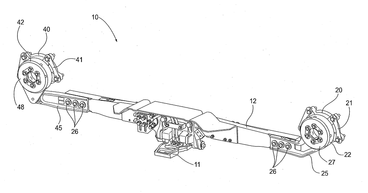
Figure 1 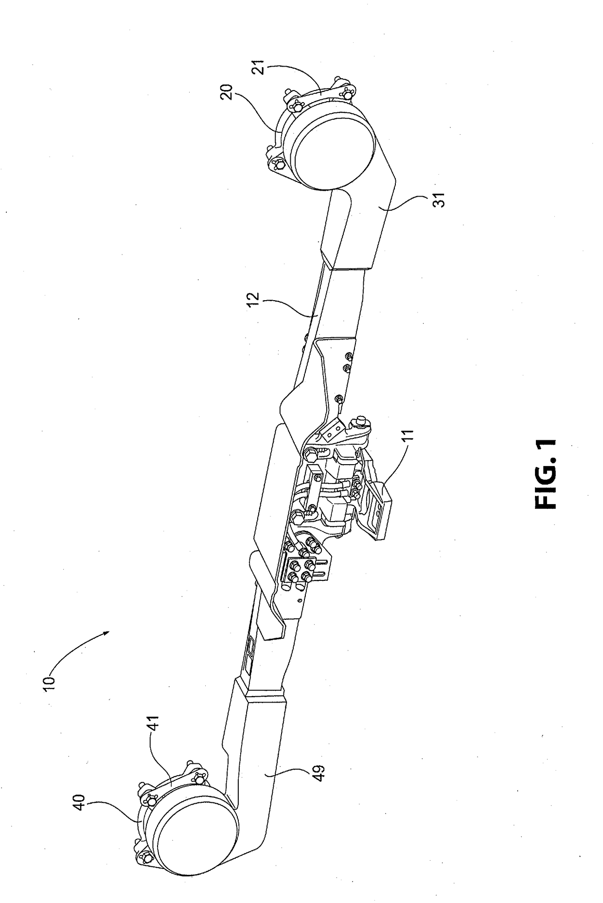
Figure 2 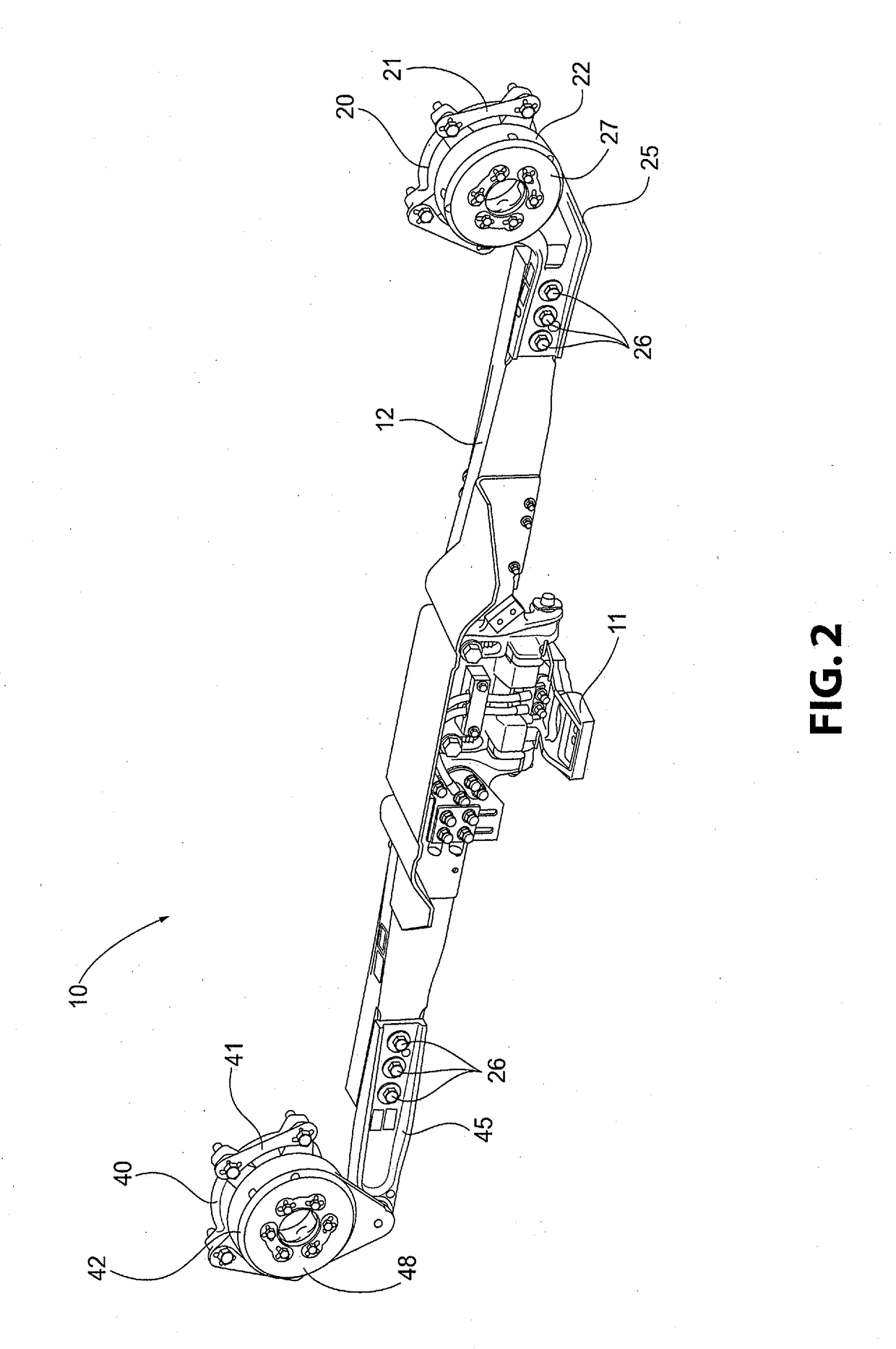
Figure 3
Abstract
Description
BACKGROUND OF THE INVENTIONField of the Invention
[0001] The present invention relates generally to an elastomeric element for mounting a current collection device on a rail vehicle. In particular, the present invention relates to retaining an elastomeric element within a housing connected to the collection device to provide a flexible support for the current collection device on the rail vehicle.Description of Related Art
[0002] Current collection devices for communicating electrical current / power to a rail vehicle from an electrified rail, commonly referred to as a “Third Rail”, which are affixed directly to the axle bearing housings of the rail vehicle are generally known in the art. Mounting the device to axle bearing housings provides a more precise relationship to the electrified rail. As the current collection device is affixed directly to the axle bearing housings, elastomeric elements are required to provide flexibility between the mount and the current device.
[0003] In prior de...
Examples
Embodiment Construction
[0033]For purposes of the description hereinafter, the terms “end”, “upper”, “lower”, “right”, “left”, “vertical”, “horizontal”, “top”, “bottom”, “lateral”, “longitudinal”, and derivatives thereof shall relate to the invention as it is oriented in the drawing figures. However, it is to be understood that the invention may assume various alternative variations and step sequences, except where expressly specified to the contrary. It is also to be understood that the specific devices and processes illustrated in the attached drawings, and described in the following specification, are simply exemplary embodiments or aspects of the invention. Hence, specific dimensions and other physical characteristics related to the embodiments or aspects disclosed herein are not to be considered as limiting.
[0034]With reference to FIGS. 1-10, a preferred and non-limiting embodiment or aspect of a current collection device 10 for a rail vehicle in accordance with the principles of the present invention...