
Method of running an air inlet system
a technology of air inlet and air filter, which is applied in the direction of engine cooling apparatus, lighting and heating apparatus, heating types, etc., can solve the problems of high cost of cooling coils and associated plants, increased fuel rate, and easy loss of output of turbines and diesel engines
Patent Information
- Authority / Receiving Office
- US · United States
- Patent Type
- Applications(United States)
- Current Assignee / Owner
- Publication Date
- 2018-11-08
Smart Images
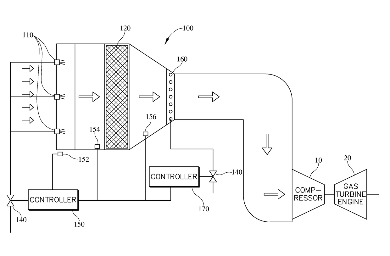
Figure 1 
Figure 2 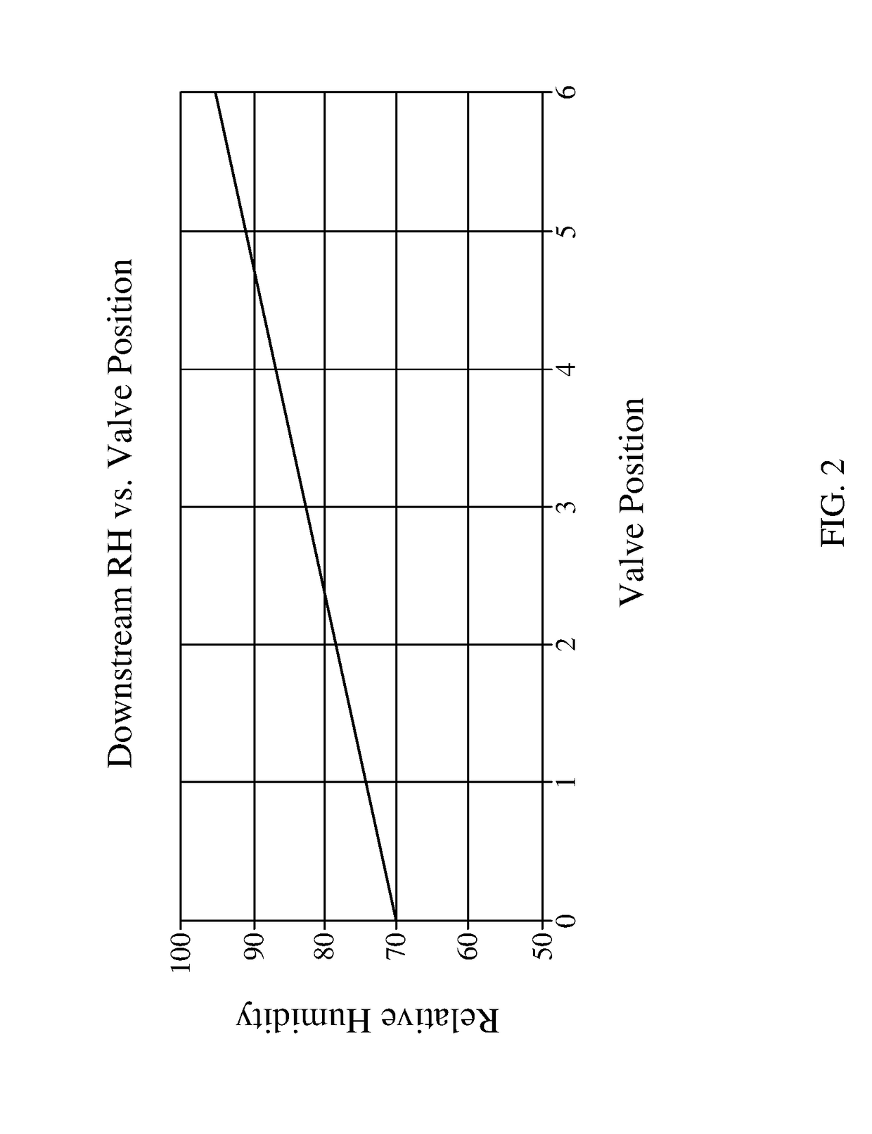
Figure 3
Abstract
Description
FIELD OF THE INVENTION
[0001] The present invention relate to a method of running an air inlet system upstream of one or more inlet air filters of a device protected by air filtration. In particular, the present invention relates to fogging systems for the cooling of inlet air to a gas turbine, diesel engine, process blower, or other motive force. Additionally, these embodiments relate to the method of control for these fogging systems.BACKGROUND OF THE INVENTION
[0002] Gas turbines and diesel engines provide motive force by compressing a near constant volume of air and igniting fuel to generate shaft power. This power may be used to drive generators used in the production of electricity or may be used to drive compressors or blowers used in oil and gas transmission or other processes. When the ambient air temperature rises, the density of the air decreases, causing the mass flow through the gas turbine to also decrease. The consequence of these is that as ambient temperature increases ...
Examples
example 1
[0090]An on-plant inlet cooling trial was conducted demonstrating that the first stage fogging, and associated control system, may control temperature and relative humidity by simply adjusting the water flow rate to the first-fogging system (e.g. rotary atomiser). The trial began by first allowing the inlet conditions to stabilize before the rotary atomiser was turned on. After the inlet conditions stabilized the rotary atomiser was started with a water flow rate of 0.5 litres per minute (A of FIG. 8), at this point the temperature immediately begins to drop from about 19.5° C. to about 18.2° C. and the inlet air relative humidity increases from about 76% to about 84%. An additional increase in water flow rate to 0.7 litres per minute (B of FIG. 8) is tested, and following this increase in the water flow rate the temperature continues to decrease to about 17.5° C. and the inlet air relative humidity increases to about 92%. Incremental decreases in the water flow rate to 0.5 litres p...
example 2
[0091]Pressure measurements were taken both before and after the filter house during the on-plant inlet cooling trial as conducted in example 1 allowing the differential pressure to be calculated. When the water rate was increased from 0.5 litres per minute to 0.7 litres per minute (B of FIG. 8) the differential pressure begins to increase to its peak of 460 Pascals. This maximum is reached and began declining prior to the incremental decrease of the water flow rate to 0.5 litres per minute (C of FIG. 8). The differential pressure continued to decrease until the after the water flow is turned off (E of FIG. 8), where it stabilizes at about 434 Pascals. The differential pressure measurements can be plotted against the relative humidity to generate a curve showing at what relative humidity measurement the differential pressure increases. The differential pressure relative humidity curve for EXAMPLES 1 and 2 is depicted in FIG. 4. The differential pressure remained constant at approxim...
example 3
[0092]In an embodiment of the two-stage cooling system herein, the ambient temperature at the inlet of the air cooling system was measured at about 50° C. Rotary atomisers were used to generate fog in the first stage of fogging. A maximum relative humidity of 90% (as determined by the differential pressure relative humidity curve) cooled the air to about 26° C. (a 24° C. temperature drop from the ambient air temperature). The second-stage fogging utilized a small plurality of low capacity high pressure nozzles, which provided further cooling of the air to about 24° C. (an additional 2° C. decrease in temperature). The air temperature dropped by a total 26° C. through use of the two-stage system, the majority (about 92%), of which occurred in the first fogging stage. Further, due to the cooling capacity of the first-stage fogging, there was no need to provide overspray cooling in the axial compressor at the compressor inlet.
[0093]Finally summarizing, the inventions also refers to a s...