
Electrical plug connector
Patent Information
- Authority / Receiving Office
- US · United States
- Current Assignee / Owner
- Publication Date
- 2019-07-11
Smart Images
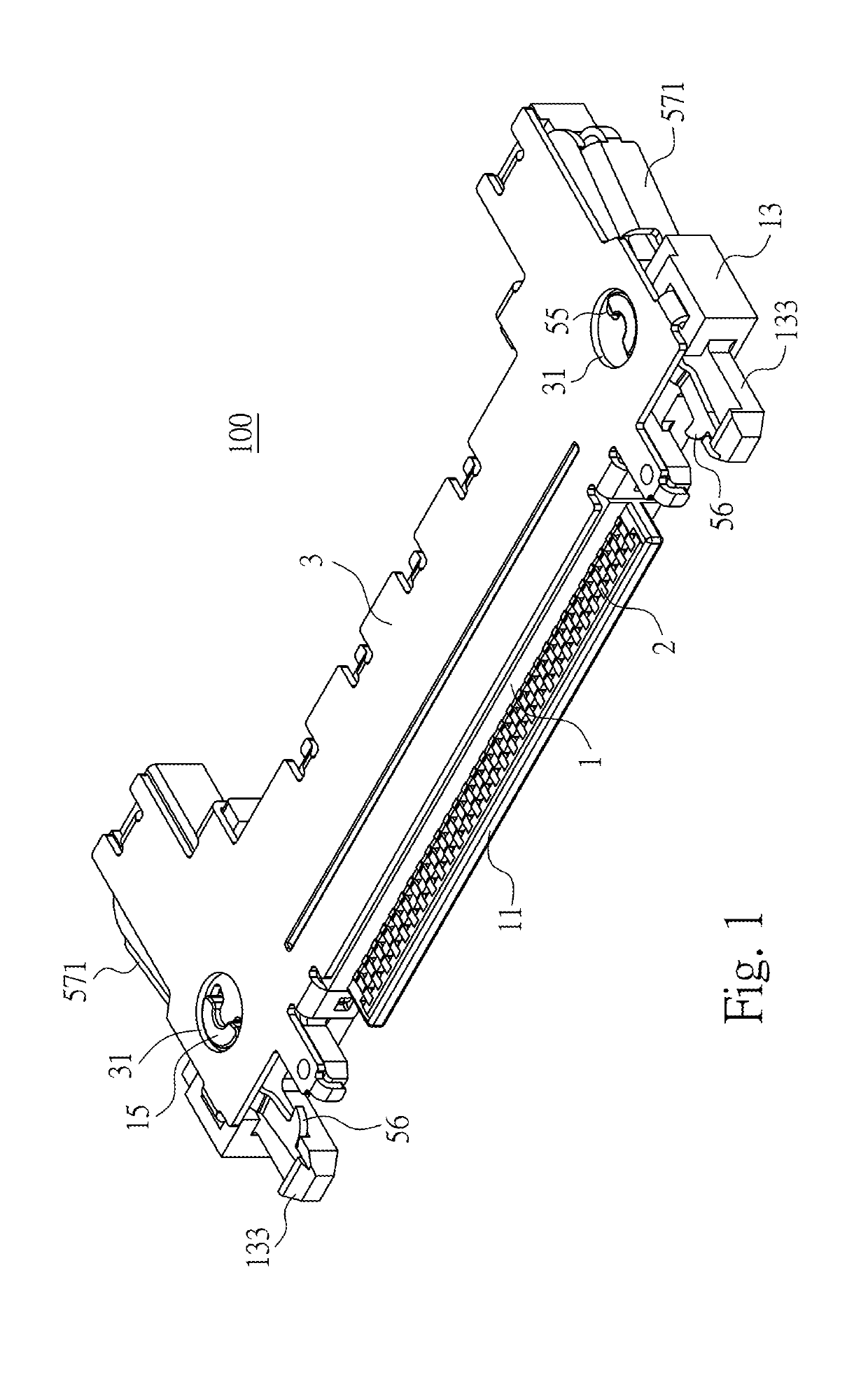
Figure 1 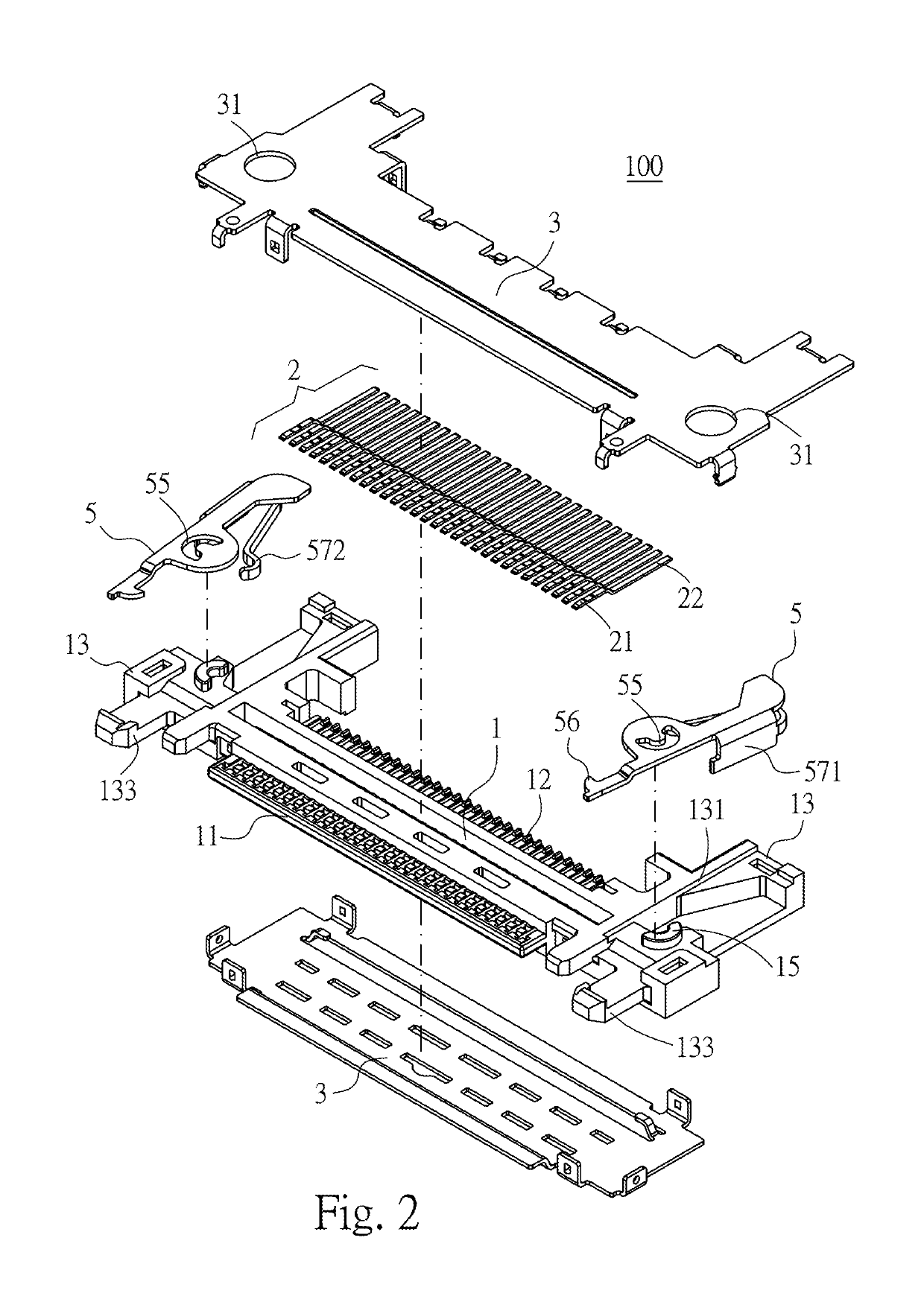
Figure 2 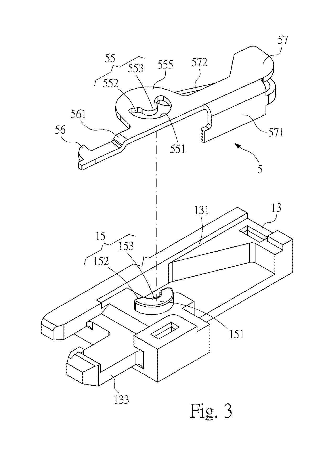
Figure 3
Abstract
Description
CROSS-REFERENCE TO RELATED APPLICATION
[0001] This non-provisional application claims priority under 35 U.S.C. § 119(a) to Patent Application No. 201820038374.6 filed in China, P.R.C. on Jan. 10, 2018, the entire contents of which are hereby incorporated by reference.FIELD OF THE INVENTION
[0002] The instant disclosure relates to an electrical connector, and more particular to an electrical plug connector.BACKGROUND
[0003] Flexible flat cable (FFC) has advantages of high flexibility and good performance in signal transmission and is widely utilized in different electronic products. The characteristics of the flexible flat cable allow the space inside the electronic product to be utilized in a flexible manner. By inserting an end portion of the flexible flat cable into an electrical plug connector, the electrical plug connector at one location in the electronic product can be mated with an electrical receptacle connector at another location in the electronic product.
[0004] An electrical plu...
Examples
first embodiment
[0030]Please refer to FIGS. 1 to 3, illustrating an electrical plug connector 100 according to the instant disclosure. FIG. 1 illustrates a perspective view thereof, FIG. 2 illustrates an exploded view thereof, and FIG. 3 illustrates a partial exploded view thereof.
[0031]In this embodiment, the electrical plug connector 100 is provided with a flexible flat cable (FFC) (not shown). In this embodiment, the electrical plug connector 100 comprises an insulated housing 1, a plurality of contact terminals 2, an outer shell 3, and a plurality of hook members 5.
[0032]Please refer to FIGS. 1 to 3. In this embodiment, the insulated housing 1 is an elongated plate. An insertion part 11 is a plate-shaped part that extends from the front surface of a body of the insulated housing 1 and has a plurality of terminal grooves formed on its upper surface, and the insertion part 11 is adapted to be inserted into an insertion opening of an electrical receptacle connector 200 (as shown in FIG. 8). A cabl...
second embodiment
[0048]Please refer to FIG. 4. In the second embodiment, the inner surface of the recessed groove 131 of each of the side arms 13 comprises a first curve portion 151 and two first abutting portions 152 together forming a hole. Namely, the first buckle structure 15 is a through hole. In this embodiment, the first buckle structure 15 forms a crescent-shaped hole (or called C-shaped hole). The first buckle structure 15 comprises the first curve portion 151, the two first abutting portions 152 at two ends of the first curve portion 151, and a first shaft portion 153 at an inner side of the first curve portion 151. The first shaft portion 153 is a protruding portion. From a top view of the first buckle structure 15, the arc length of the first buckle structure 15 is greater than the perimeter of a half circle, but embodiments are not limited thereto. In some embodiments, the arc length of the first buckle structure 15 may be equal to or less than the perimeter of a half circle.
[0049]Pleas...