
Control Device for DC-DC Converter
Patent Information
- Authority / Receiving Office
- US · United States
- Current Assignee / Owner
- Publication Date
- 2019-09-12
Smart Images
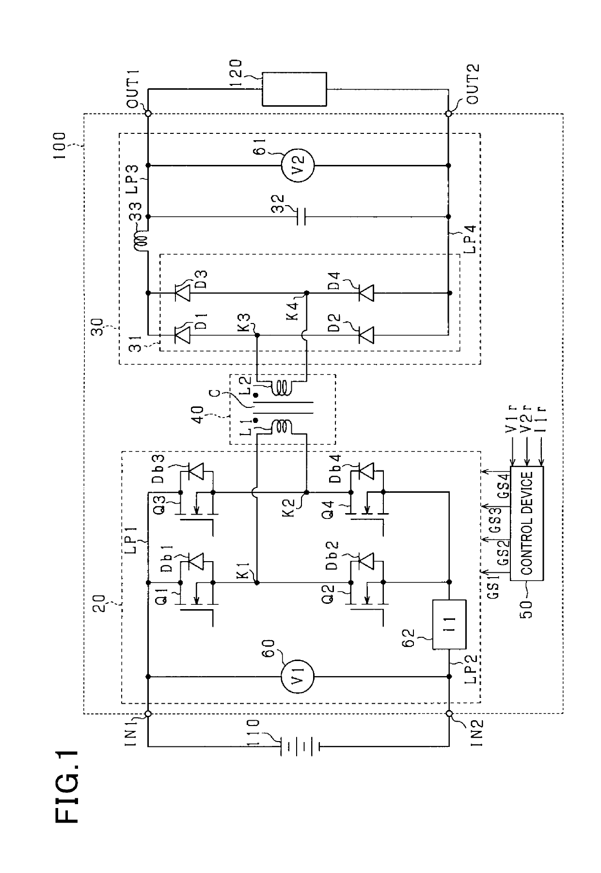
Figure 1 
Figure 2 
Figure 3
Abstract
Description
CROSS-REFERENCE TO RELATED APPLICATION
[0001] This application is based on and claims the benefit of priority from earlier Japanese Patent Application No. 2018-40053 filed Mar. 6, 2018, the description of which is incorporated herein by reference.BACKGROUNDTechnical Field
[0002] The present disclosure relates to a control device applied to an insulated DC-DC converter including a transformer.Related Art
[0003] A DC-DC converter including a transformer is subject to iron loss depending on the material, shape, or the like of a core.
[0004] There is a need for a control device for a DC-DC converter, which is capable of reducing iron loss occurring in a transformer of an insulated DC-DC converter.SUMMARY
[0005] One aspect of the present disclosure provides a control device applied to an insulated DC-DC converter including a transformer including input winding and output winding magnetically coupled together via a core and drive switches connected to the input winding. The control device operates ...
Examples
first embodiment
[0018]A DC-DC converter according to a first embodiment will be described. The DC-DC converter is mounted in a vehicle and reduces or increases a DC voltage supplied from a battery used as a DC power supply and supplies power to an apparatus used as a feeding target.
[0019]FIG. 1 is a diagram of a configuration of a DC-DC converter 100 according to the present embodiment. The DC-DC converter 100 includes a first input terminal IN1 to which a cathode terminal of the battery 110 is connected and a second input terminal IN2 to which an anode terminal of the battery 110 is connected. Furthermore, the DC-DC converter 100 includes a first output terminal OUT1 to which a cathode terminal of an apparatus 120 is connected and a second output terminal OUT2 to which an anode terminal of the apparatus 120 is connected. The battery 110 is, for example, a battery pack including a plurality of battery cells connected together in series. The apparatus 120 includes at least one of a battery, an in-ve...
modified example 1 of first embodiment
[0064]In Modified Example 1 of the first embodiment, components differing from the components of the first embodiment will mainly be described.
[0065]FIG. 7 illustrates the switching frequency fsw set based on the output voltage V2r. The abscissa axis indicates the output voltage V2r, and the ordinate axis indicates the switching frequency fsw. In FIG. 7, a dashed line represents changes of the reference frequency Fs and a solid line represents changes of the switching frequency fsw in the present embodiment in a case where the target value of the iron loss Pi is assumed to be the target iron loss value Tpi. FIG. 8 illustrates changes of the iron loss Pi in accordance with the changes of the switching frequency fsw illustrated in FIG. 7. The abscissa axis indicates the output voltage V2r, and the ordinate axis indicates the iron loss Pi.
[0066]In the present embodiment, the frequency increase rate Δf of the switching frequency fsw set by the control device 50 is set to such a value as...
modified example 2 of first embodiment
[0071]The frequency increase rate Δf of the switching frequency fsw may be set to such a value as makes the iron loss Pi of the core C constant. In this case, it is sufficient that the reference frequency Fs corresponding to the target iron loss value Tpi, used as the target value, is calculated and that information including the calculated reference frequency Fs in association with the output voltage V2r is be stored in the storage unit as table information. Also in the present modified example, it is sufficient that the reference frequency Fs is set to a value increasing with the value of the output voltage V2r and that the reference frequency Fs is set to increase the frequency increase rate Δf with the output voltage V2r.
Second Embodiment
[0072]In a second embodiment, components differing from the components of the first embodiment will mainly be described. In the second embodiment, the same components as the corresponding components of the first embodiment are denoted by the sa...