
A parallel control method for three-phase two-level inverters with isolation transformer
A technology of isolation transformer and control method, which is applied in the direction of single-network parallel feeding arrangement, etc., and can solve problems such as complex control algorithm and difficult implementation
Patent Information
- Authority / Receiving Office
- CN · China
- Patent Type
- Patents(China)
- Current Assignee / Owner
- Publication Date
- 2014-10-29
Smart Images
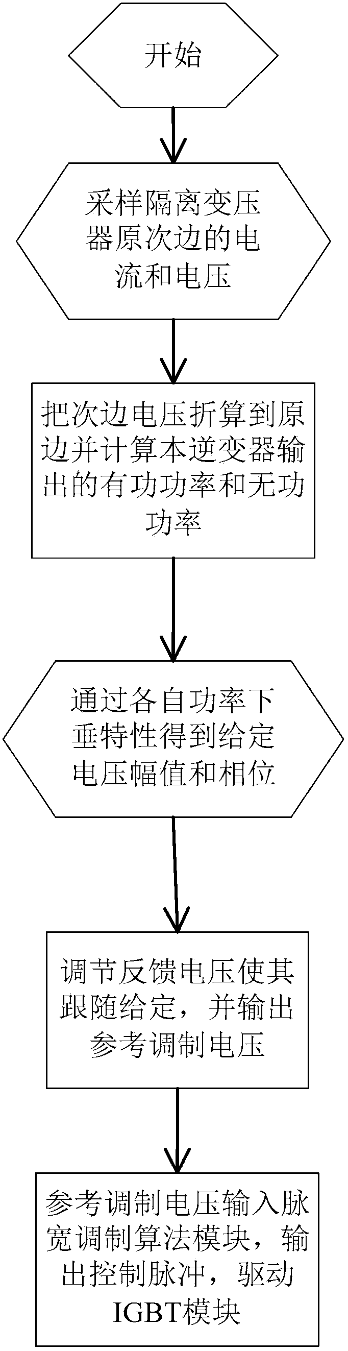
Figure 1 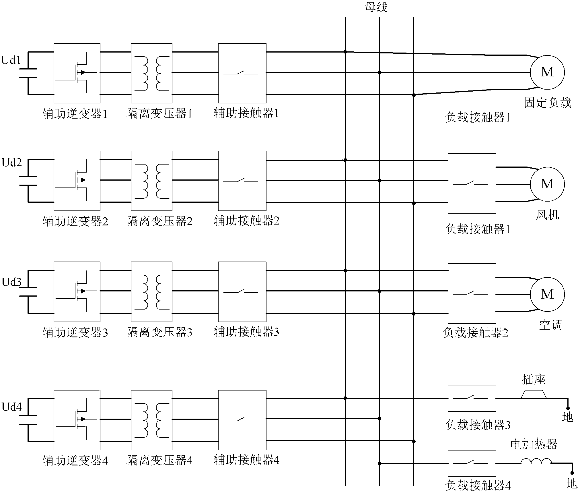
Figure 2 
Figure 3
Abstract
Description
technical field
[0001] The invention mainly relates to the field of inverter parallel control design, in particular to a three-phase two-level inverter parallel control method with an isolation transformer. Background technique
[0002] Taking the auxiliary power supply system of the EMU as an example, as a part of the auxiliary power supply system of the EMU, the auxiliary inverter is mainly used to provide stable single-phase or three-phase AC power for air conditioning units, ventilation devices, air compressors, electric heaters, passenger rooms, etc. Used for AC auxiliary loads such as lighting. At present, the auxiliary inverters of most vehicles are single-unit operation, with large capacity and low reliability. Therefore, in order to improve the power supply reliability of the EMU auxiliary power supply system and provide redundancy for the auxiliary power supply, multiple auxiliary inverters can be operated in parallel.
[0003] The existing inverter parallel cont...
Examples
Embodiment Construction
[0045] The present invention will be further described in detail below in conjunction with the accompanying drawings and specific embodiments.
[0046] Such as figure 1 As shown, the present invention has a three-phase two-level inverter parallel control method with an isolation transformer, and its steps are:
[0047] 1. Each auxiliary inverter is connected to an isolation transformer: through the adjustment of the auxiliary inverter, the direct current is modulated into an alternating current with a certain amplitude and frequency, and then is stepped down and filtered by the isolation transformer to supply the AC auxiliary load on the EMU. Use; the secondary side of the isolation transformer is connected to the busbar on the EMU through an auxiliary contactor.
[0048] see figure 2 , is a schematic diagram of forming a high-power auxiliary inverter parallel system for an EMU in a specific application example of the present invention. In this example, there are four auxi...