
Power supply system and method thereof
Patent Information
- Authority / Receiving Office
- US · United States
- Current Assignee / Owner
- Publication Date
- 2005-07-05
Smart Images
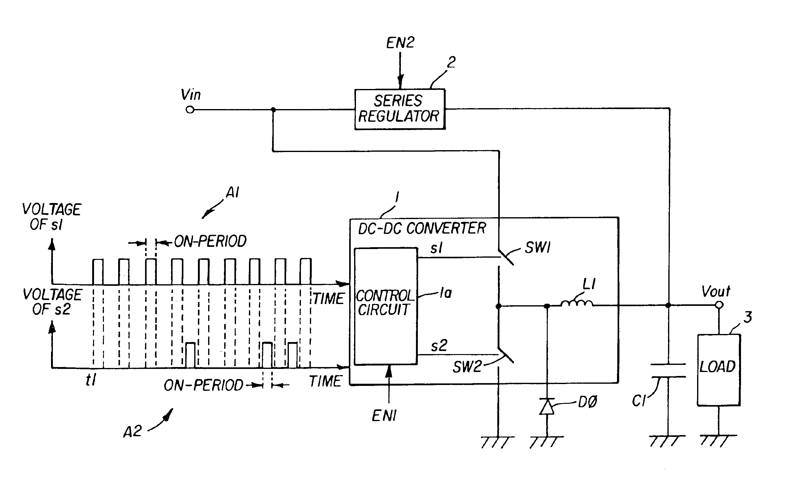
Figure 1 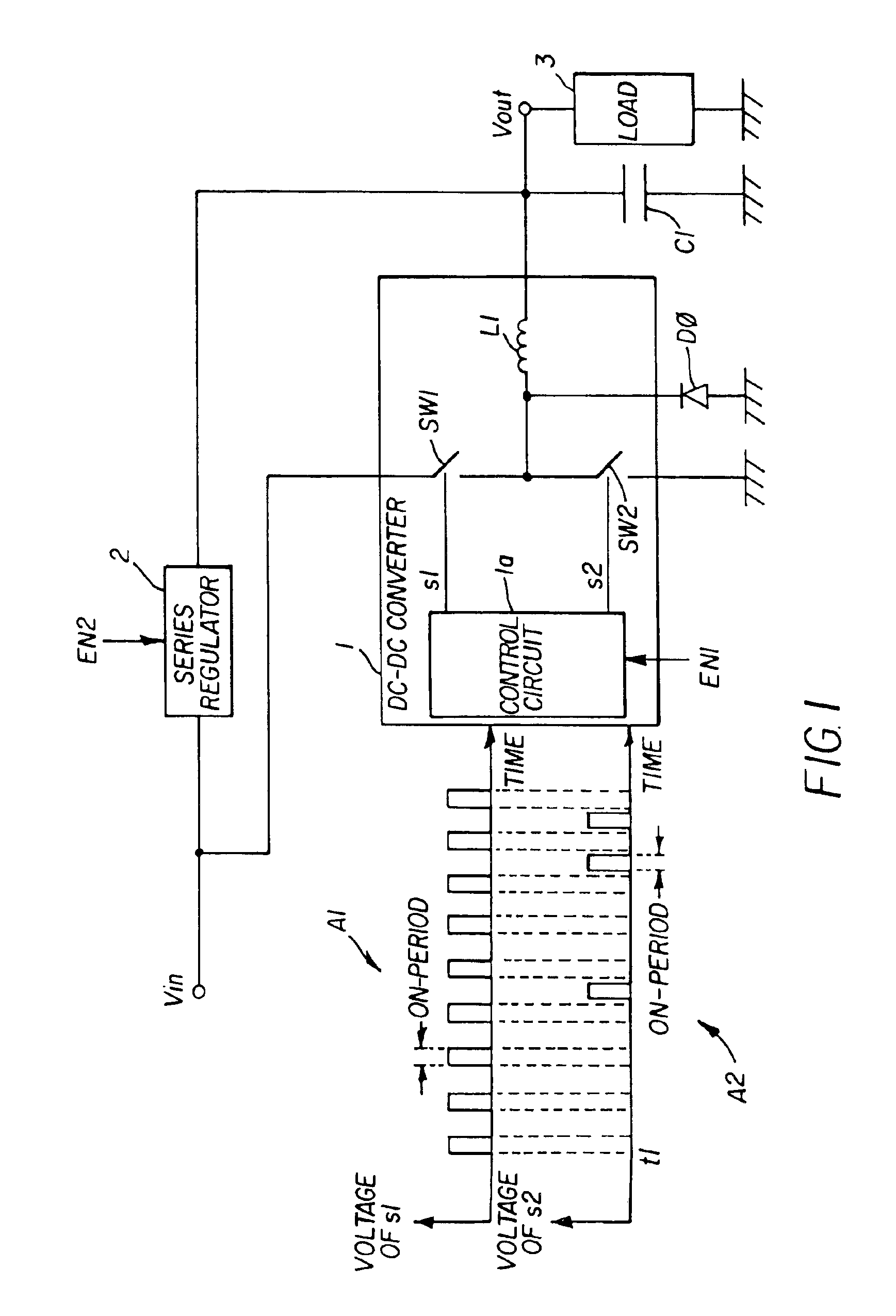
Figure 2 
Figure 3
Abstract
Description
BACKGROUND
[0001] A power supply mounted on an electronic apparatus steps down an external voltage to a level appropriate for the electronic circuit in the apparatus. Power efficiency of some of such power supplies varies depending on the loading condition of the output terminal of the power supply. For example, a DC-DC converter that steps down the voltage by means of PWM control exhibits low power efficiency when the loading is light and high power efficiency when the loading is heavy. This is due to driving losses generated at the ON-OFF operation of semiconductor switches in the DC-DC converter. On the other hand, a series regulator performs at constant power efficiency independently of the loading.
[0002] There are known power supply systems that exchange a power source between a DC-DC converter and a series regulator corresponding to the loading, as disclosed in Japanese Unexamined Patent Application Publication No. H11-341797 and No. 2002-112457. When the load connected to the po...
Examples
Embodiment Construction
[0020]FIG. 1 shows a principle of a power supply system according to the present invention. The power supply system comprises a DC-DC converter 1 and a series regulator 2. The DC-DC converter 1 includes a control circuit 1a, switching elements SW1 and SW2, a free wheeling diode D0, and an inductor L1. The FIG. 1 also shows voltage waveforms A1 and A2 of switching signals s1 and s2 that are output from the control circuit 1a. The DC-DC converter 1 and the series regulator 2 are connected parallel to each other. Output terminals of the DC-DC converter 1 and the series regulator 2 connect to a capacitor C1 and a load 3. The DC-DC converter 1 steps down the input voltage Vin and outputs to the load 3 when a first selection signal EN1 is input thereto. The series regulator 2 steps down the input voltage Vin and outputs to the load 3 when a second selection signal EN2 is input thereto.
[0021]The first selection signal EN1 or the second selection signal EN2 is input to the DC-DC converter 1...