
Connector assembly and method of manufacture
a technology of connecting rods and connectors, applied in the field of connecting rods, can solve the problems of exacerbated problems, no longer guaranteed assembly action, and crucial elastic properties of assembly materials, and achieve the effects of less force, less material safety, and less for
Patent Information
- Authority / Receiving Office
- US · United States
- Current Assignee / Owner
- Publication Date
- 2005-07-26
- Estimated Expiration
- Not applicable · inactive patent
Smart Images
Figure 1 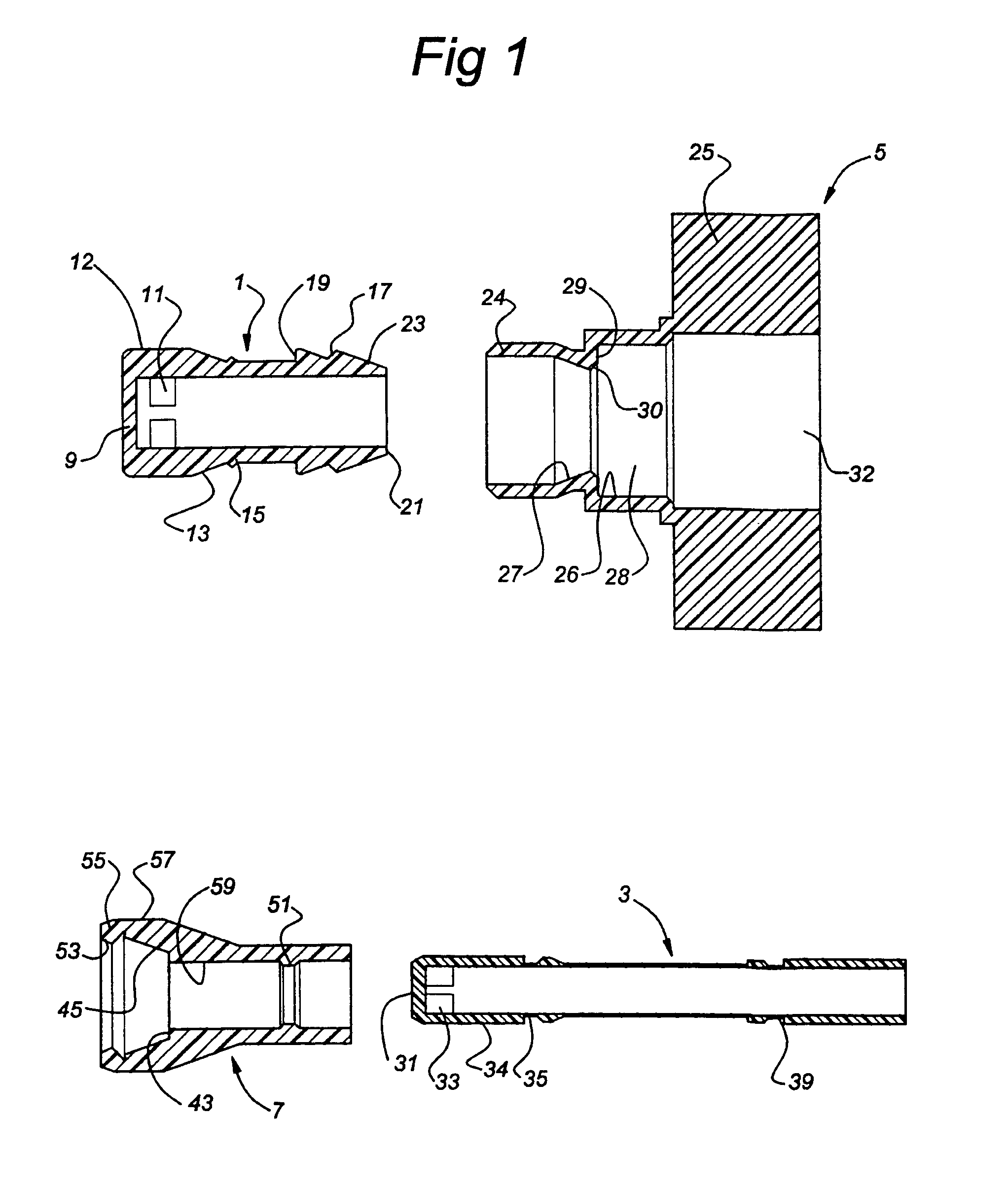
Figure 2 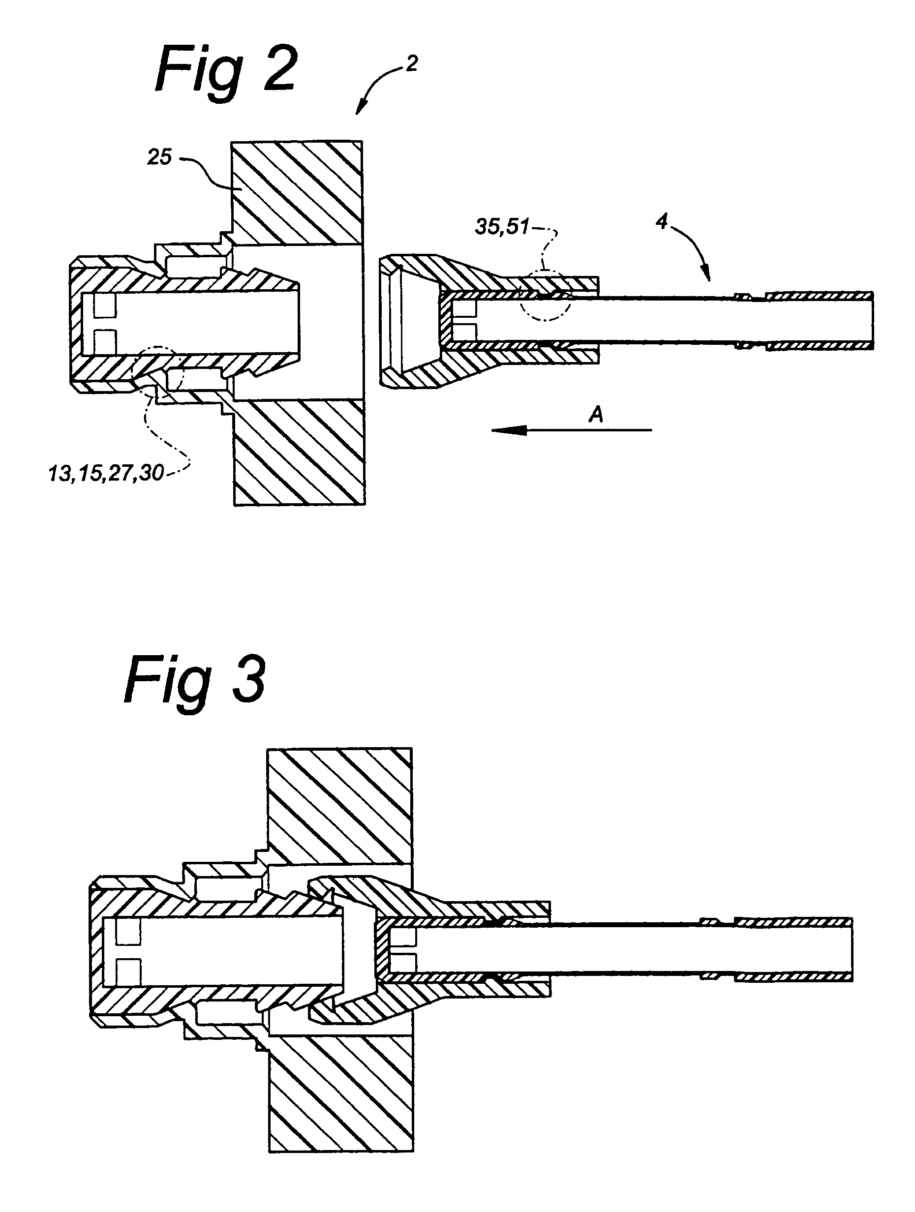
Figure 3
Abstract
Description
BACKGROUND AND SUMMARY OF THE INVENTION
[0001] The invention relates to a connector assembly for optionally allowing a free-flowing medium to pass through, comprising:
[0002] a hollow female element with a transverse closure wall and passage openings which are formed in the side wall,
[0003] a male element which can be inserted into the female element and can be coupled thereto,an adapter socket, inside which the female element can be displaced in axial direction between a position in which it closes off the flow of medium and in which the passage openings are closed off by the adapter socket, and a position in which it allows medium to flow through and in which the passage openings are not closed off by the adapter socket, in which assembly the female element is provided, at a distance from the transverse closure wall, with connecting means which can form a connection with connecting means arranged on the male element or a coupling piece coupled to the male element, and in which assembly...
Examples
Embodiment Construction
[0026]The connector assembly comprises a closure assembly 2 and an opening assembly 4, cf. FIG. 2. The closure assembly 2 comprises a female element 1, in the form of a cap, and an adapter socket 5 in which the said female element 1 is slideably accommodated. The opening assembly 4 comprises a tubular male element 3 and a coupling piece 7 in which the said male element 3 is slideably positioned. In FIG. 1, the four components of the assembly are shown separately and the various details are denoted by reference numerals.
[0027]FIG. 2 shows how elements are positioned with respect to one another in the starting situation. The female element 1 is accommodated in the adapter socket 5 in order to form the closure assembly 2. The male element 3 together with the coupling piece 7 forms the opening assembly 4.
[0028]The female element 1 comprises an end wall 9 and four openings 11 which are arranged cylindrically near the said end wall 9. Furthermore, the female element is provided with a sto...