
Antenna diversity receiver
Patent Information
- Authority / Receiving Office
- US · United States
- Current Assignee / Owner
- Publication Date
- 2005-08-16
- Estimated Expiration
- Not applicable · inactive patent
Smart Images
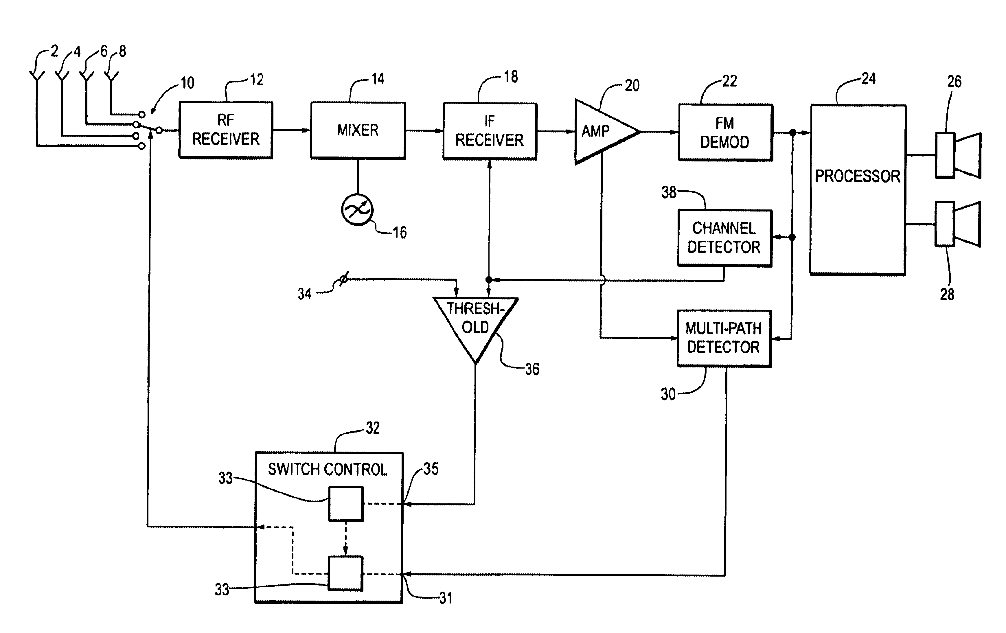
Figure 1 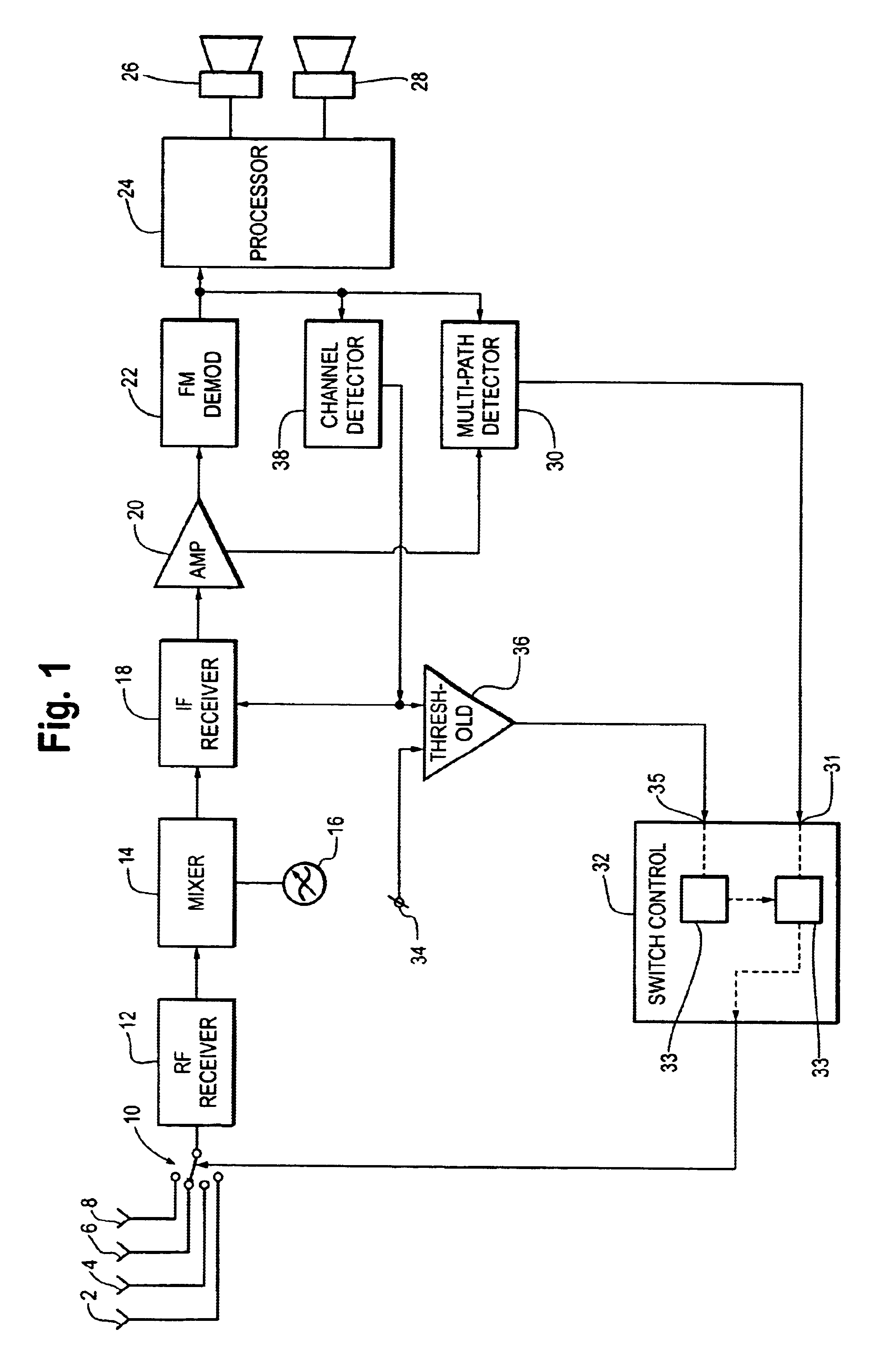
Figure 2
Abstract
Description
FIELD OF INVENTION
[0001] This invention relates to an antenna diversity receiver which has a selective switching circuit for coupling one of a plurality of antennas to a RF receiver input, as well as a multipath detector for controlling the selective switching circuit.BACKGROUND OF INVENTION
[0002] The reception of a wanted RF broadcast transmitter signal may be disturbed or otherwise deteriorated by various phenomena, such as multipath reception and / or adjacent channel interferences. In general, multipath reception is caused by signal reflections at and / or against environmental physical obstacles such as mountains, trees, buildings, fences and the like. Due to such signal reflections a RF broadcast signal may arrive at a certain reception location through various different signal paths which result in different amplitude and phase conditions. The summation of these multipath signals at the antenna of the receiver results in unpredictable signal amplitude and / or phase distortions. Thes...
Examples
Embodiment Construction
[0018]While the present invention is capable of embodiment in various forms, there is shown in the drawings and will hereinafter be described a presently preferred embodiment with the understanding that the present disclosure is to be considered as an exemplification of the invention, and is not intended to limit the invention to the specific embodiment illustrated.
[0019]FIG. 1 shows an antenna diversity FM receiver having first to fourth antennas 2, 4, 6 and 8 coupled through an antenna selective switching circuit 10 to a RF receiver input circuit 12. The RF receiver input circuit 12 is followed by a mixer device 14 which is supplied with a tunable local oscillator signal from an oscillator circuit 16, a variable bandwidth intermediate frequency (IF) selector circuit 18 (selective IF circuit), a IF amplifier 20, an FM demodulator 22 and a baseband modulation signal processor 24. The baseband modulation signal processor 24 is coupled to stereo left and stereo right signal reproducin...