
Method and instrument for microscopy
a microscopy and instrument technology, applied in the field of illuminating objects, can solve the problems of disruptive interference phenomena, inflexible use of known illuminating devices, and inability to adapt to the use of laser-based illuminating devices and illuminating methods,
Patent Information
- Authority / Receiving Office
- US · United States
- Patent Type
- Patents(United States)
- Current Assignee / Owner
- Publication Date
- 2006-09-19
- Estimated Expiration
- Not applicable · inactive patent
Smart Images
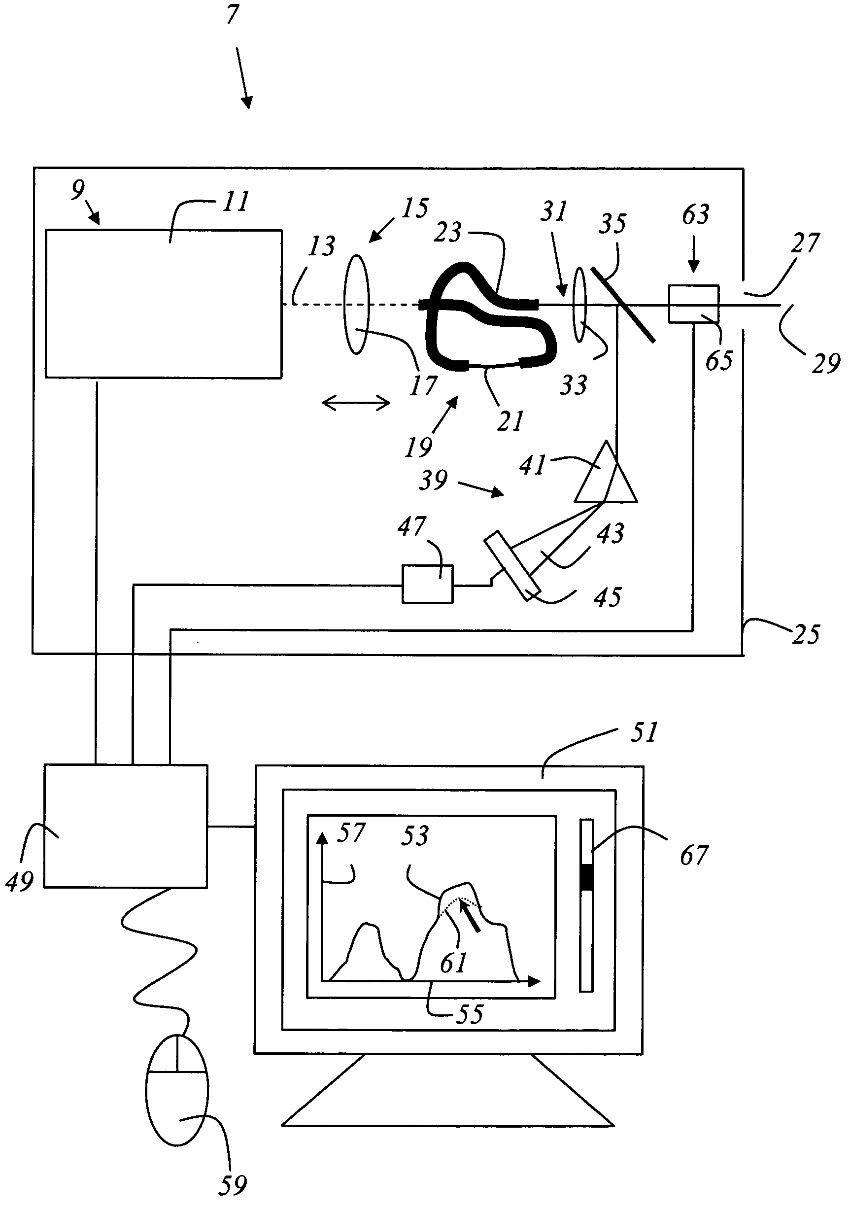
Figure 1 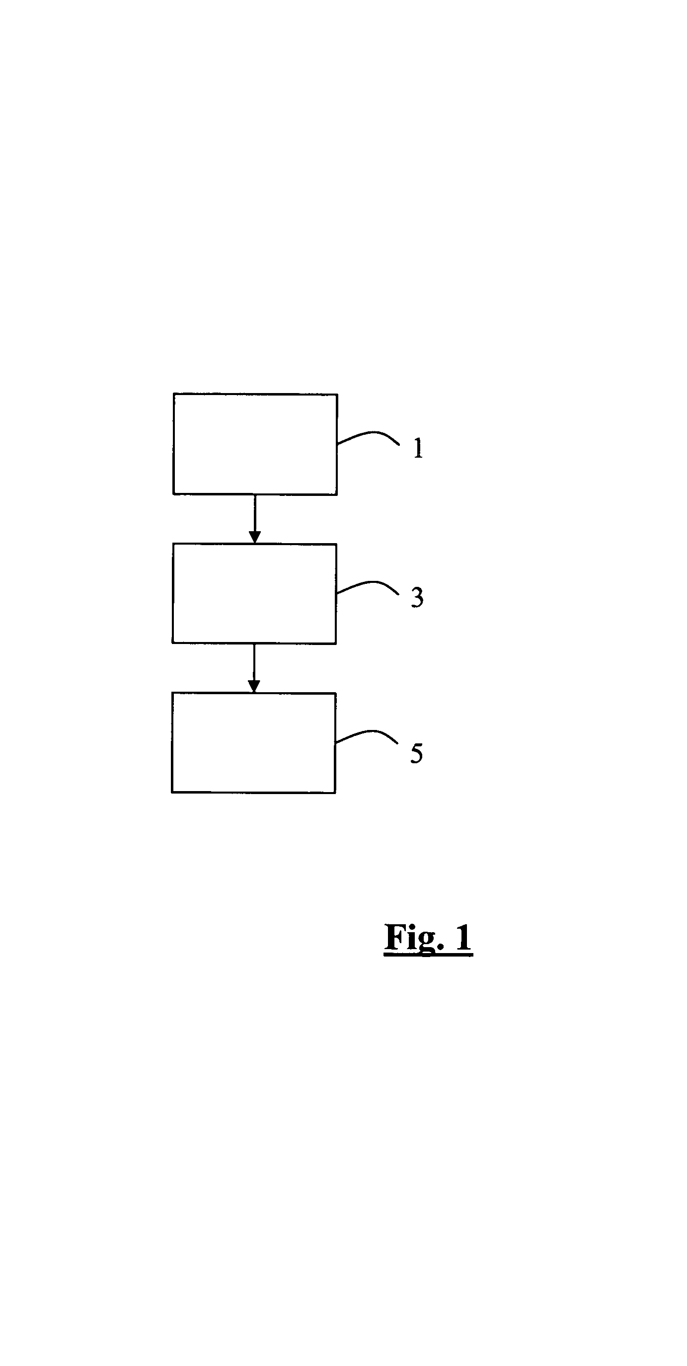
Figure 2 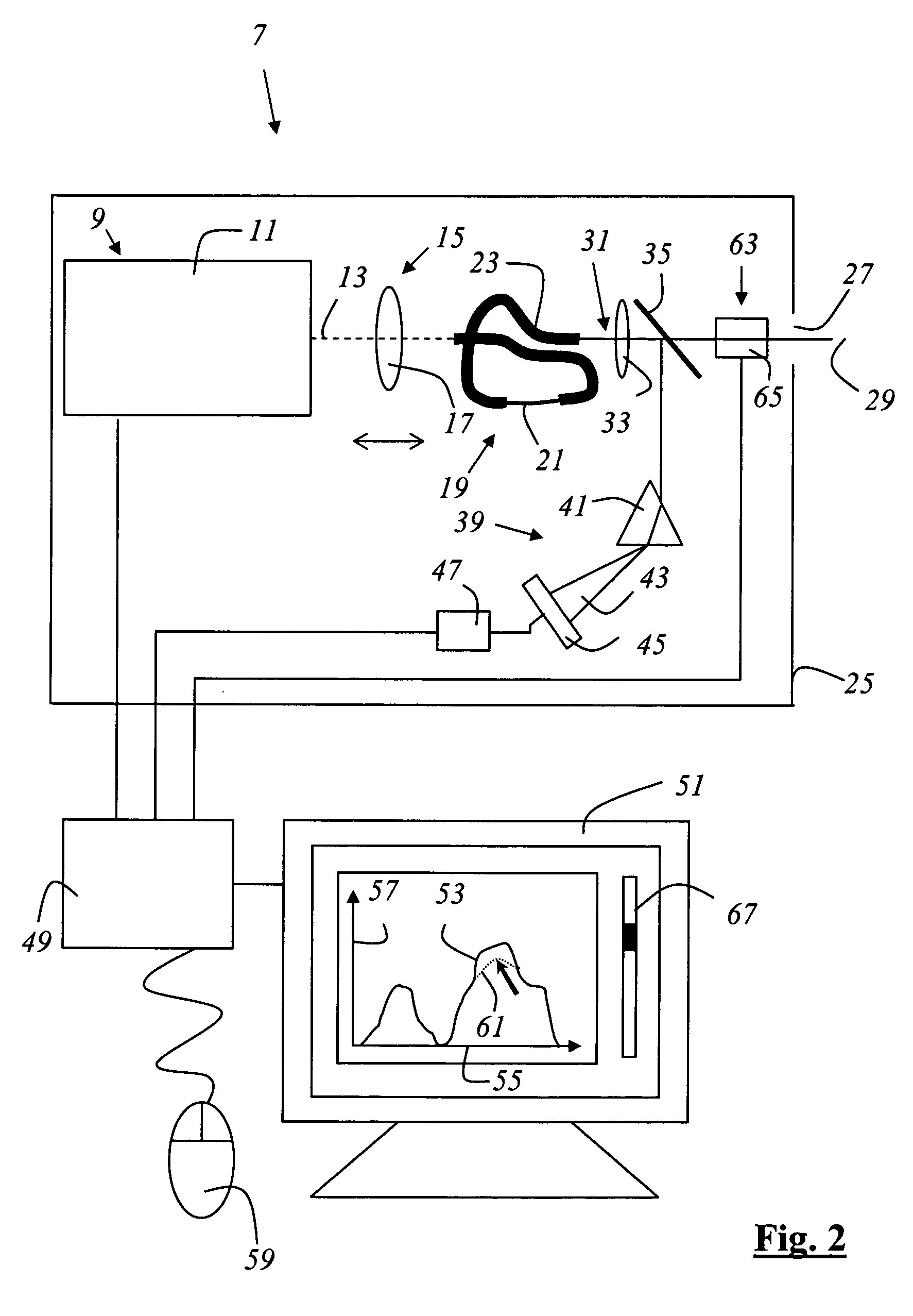
Figure 3
Abstract
Description
CROSS REFERENCE TO RELATED APPLICATIONS
[0001] This invention is a continuation of U.S. patent application Ser. No. 09 / 881,049, filed Jun. 15, 2001, now U.S. Pat. No. 6,898,367, which claims priority to German patent applications 100 30 013.8 and 101 15 487.9 and 101 15 589.1 and 101 15 486.0 and 101 15 488.7 and 101 15 509.3 and 101 15 577.8 and 101 15 590.5, all of which are hereby incorporated by reference herein.
[0002] This application refers to U.S. patent application Ser. No. 09 / 881,048, now abandoned, entitled “ARRANGEMENT FOR STUDYING MICROSCOPIC PREPARATIONS WITH A SCANNING MICROSCOPE”, which is incorporated herewith.
[0003] This application refers to U.S. patent application Ser. No. 09 / 881,046, now U.S. Pat. No. 6,611,643, entitled “ILLUMINATING DEVICE AND MICROSCOPE”, which is hereby incorporated by reference herein.
[0004] This application refers to U.S. patent application Ser. No. 09 / 880,825, now U.S. Pat. No. 6,567,164, entitled “ENTANGLED-PHOTON MICROSCOPE AND CONFOCAL MICRO...
Examples
Embodiment Construction
[0056]FIG. 1 shows a flow chart of the method according to the invention. In a first step, the light from a laser is injected 1 into a microstructured optical element that spectrally broadens the light. In this case, the light is guided to the microstructured optical element, for example with the aid of mirrors, and is preferably focused onto the microstructured optical element using a variable lens. In a second step, the light emerging from the microstructured optical element is shaped 3 to form an illumination light beam, preferably with the aid of optical means which are configured as lens systems. In a further step, the illumination light beam is directed 5 onto the object.
[0057]FIG. 2 shows an illuminating instrument 7 which contains a laser 9 that is embodied as a mode-locked Ti:sapphire laser 11 and emits a light beam 13, which is shown in dashes, with the property of an optical pulse train. The width of the light pulses is approximately 100 fs with a repetition rate of appro...