
Cleaning brush structure with replaceable brush hair plate
a brush and hair plate technology, applied in the field of cleaning brushes, can solve the problems of occupying too much storage space, wasting earth resources, and unable to remove, replace or clean the hair plate after a long time us
Patent Information
- Authority / Receiving Office
- US · United States
- Patent Type
- Patents(United States)
- Current Assignee / Owner
- Publication Date
- 2006-09-26
- Estimated Expiration
- Not applicable · inactive patent
Smart Images
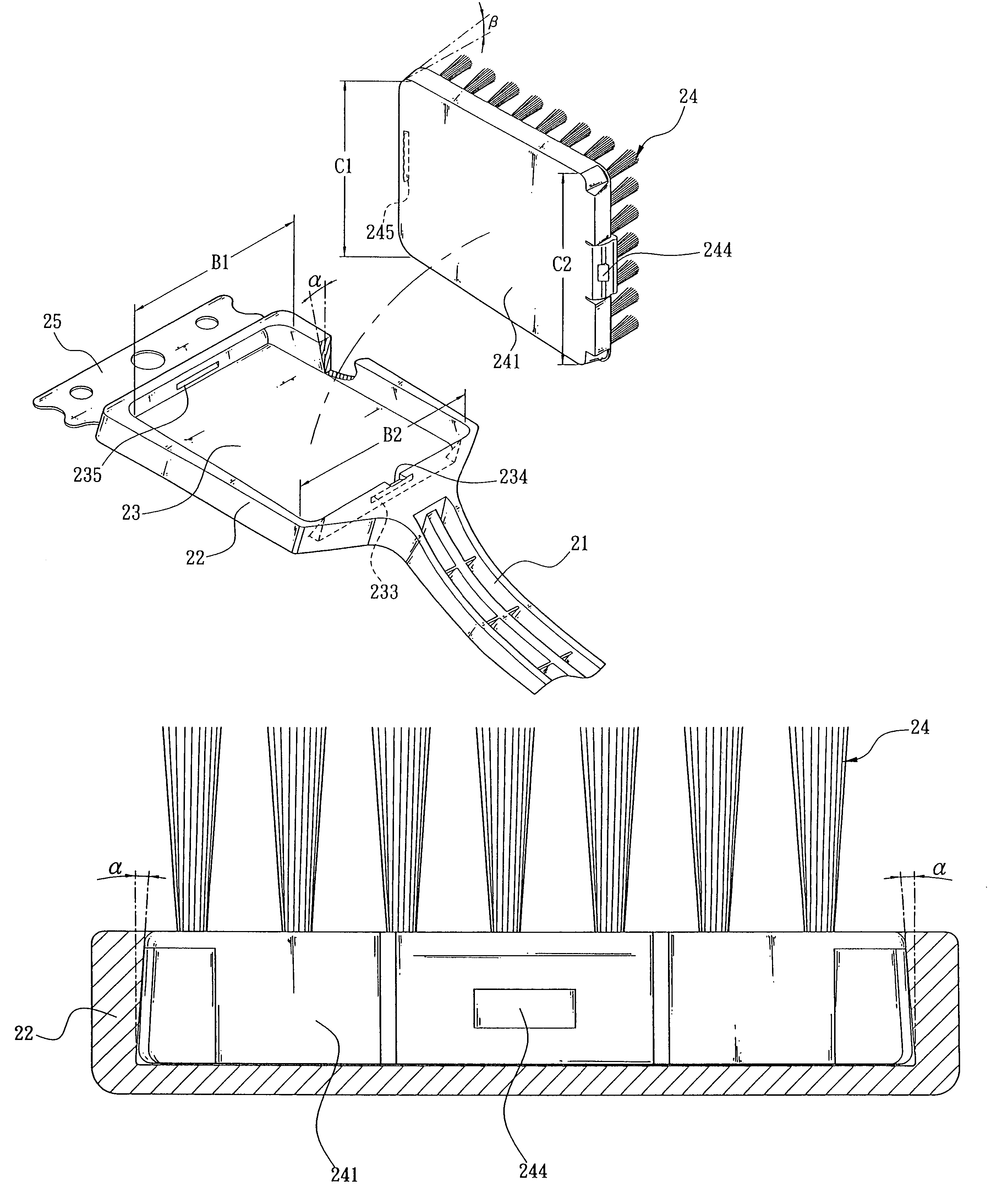
Figure 1 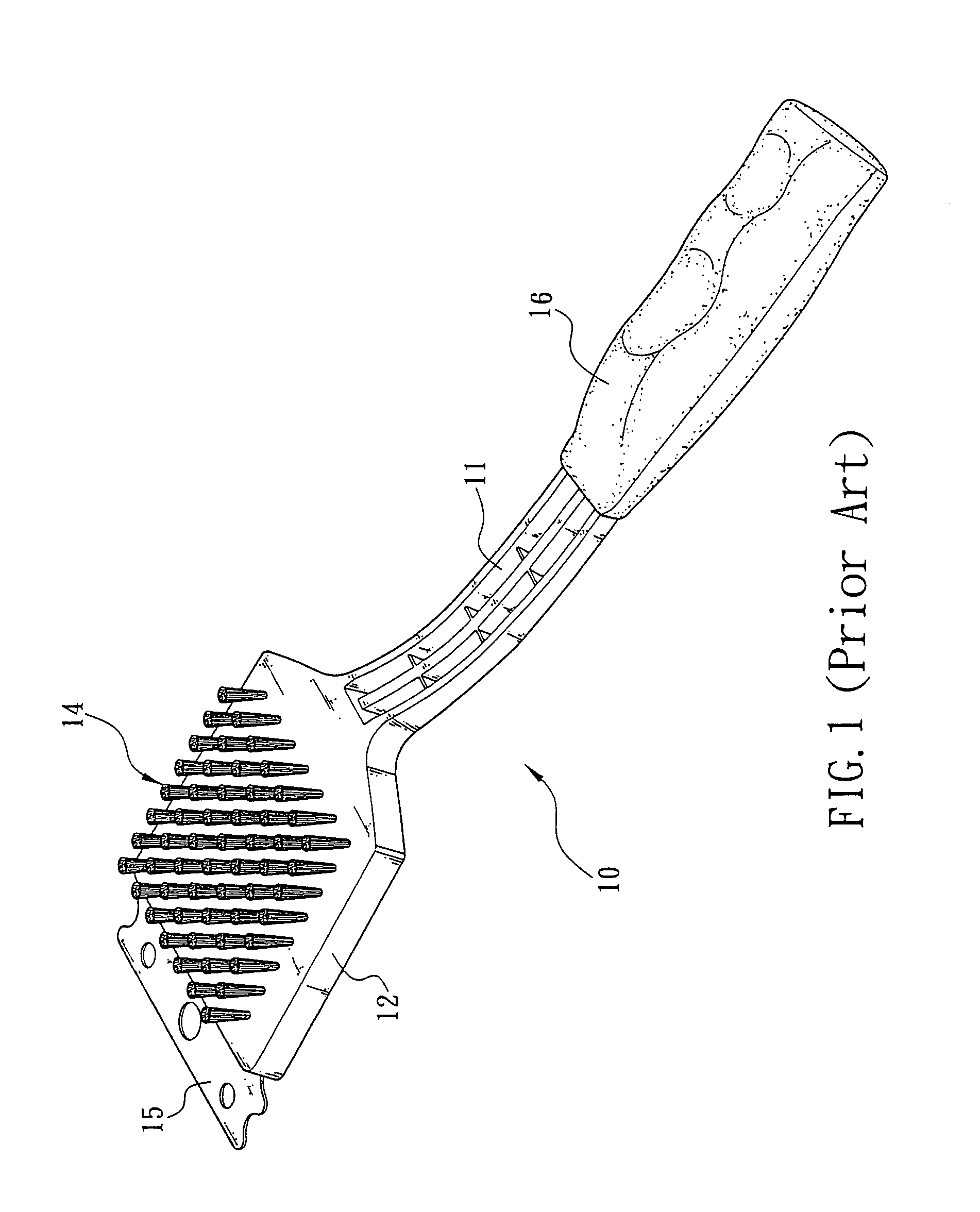
Figure 2 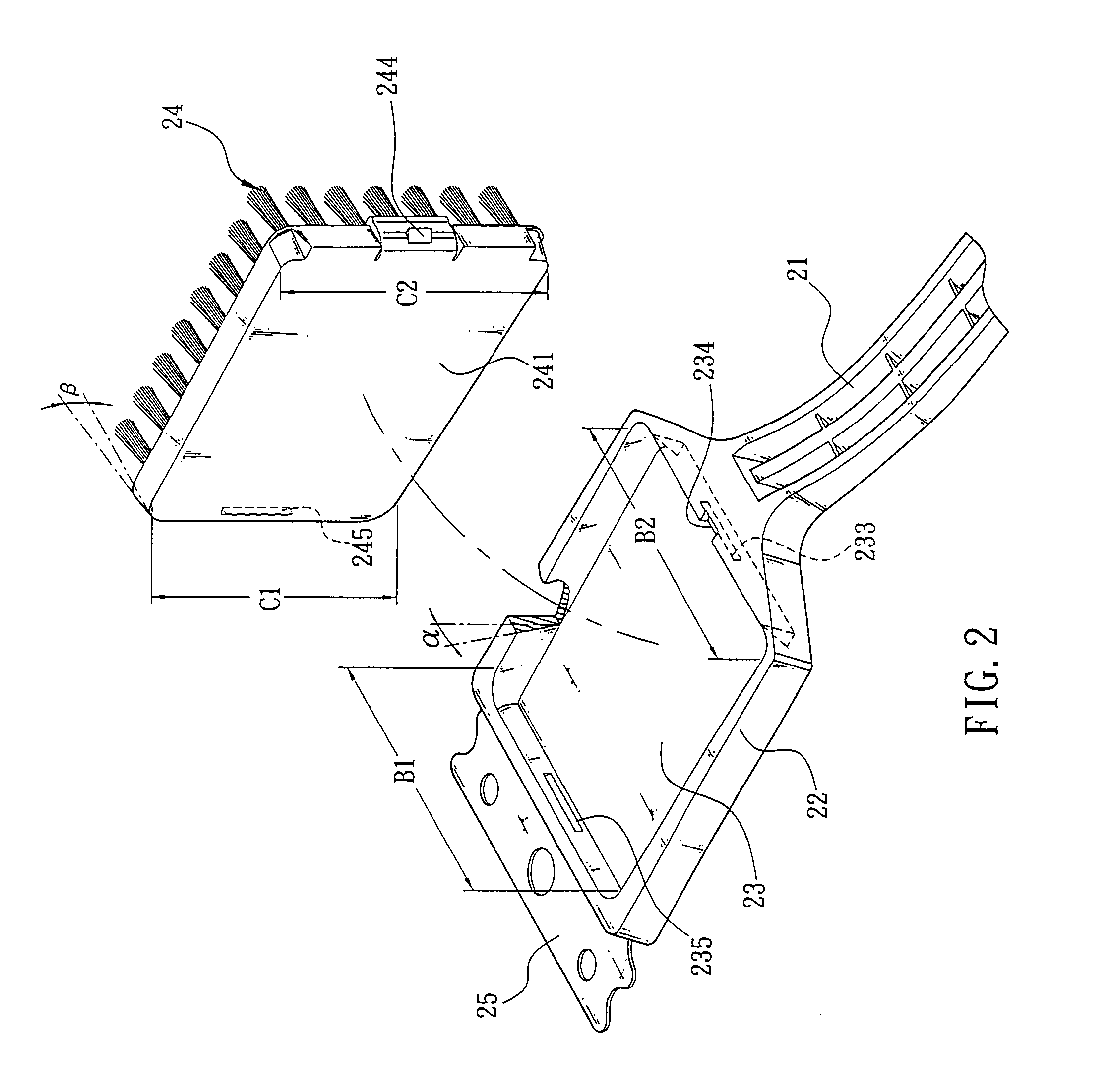
Figure 3
Abstract
Description
FIELD OF THE INVENTION
[0001] The present invention generally relates to cleaning brushes, more particularly to a cleaning brush structure having a replaceable brush hair plate.BACKGROUND OF THE INVENTION
[0002] In the area of general cleaning accessories, a brush used for cleaning is very common to everyone, and one of these cleaning brushes will be described briefly below.
[0003] Please refer to FIG. 1. A cleaning brush 10 comprises a slender rod body 11, a plate member 12 extended from one end of the slender rod body 11, a brush hair plate 14 integrally coupled onto the plate member 12 to form a brush hair plate.
[0004] Further, the plate member 12 comprises a metal plate 15 protruded from the front of the plate member 12 for removing a tough dirt or stain. The brush hair plate 14 comprises a plurality of brush hairs or scrubbing cloths; and the embodiment as shown in FIG. 1 adopts a plurality of brush hairs. Further, the slender rod body 11 has a handle 16 at the other end to facilitate...
Examples
Embodiment Construction
[0018]Please refer to FIGS. 2, 3 and 4 for a cleaning brush structure with a replaceable brush hair plate of the present invention. The cleaning brush 20 comprises a slender rod body 21, a plate member 22 extended from one end of the slender rod body 21 and an accommodating groove 23 disposed on one side of the plate member 22, wherein the accommodating groove 23 is tapered in width from a rear end B2 to a corresponding front end B1 such that the internal walls on two opposite sides at the positions adjacent to the front end B1 slightly face a bottom surface inside the accommodating groove 23 to define an opening above the accommodating groove 23. The two internal walls are inclined to slightly face the bottom of the accommodating groove 23 at an angle of inclination α that increases from the rear end B2 to the front end B1. Therefore, the opening at the front end B1 is slightly smaller than the bottom as shown in FIGS. 2 and 3. A first latch groove 233 is disposed in a wall at the ...