
Device and method for securing a punch tool to a ram portion of a press brake
Patent Information
- Authority / Receiving Office
- US · United States
- Current Assignee / Owner
- Publication Date
- 2007-01-30
Smart Images
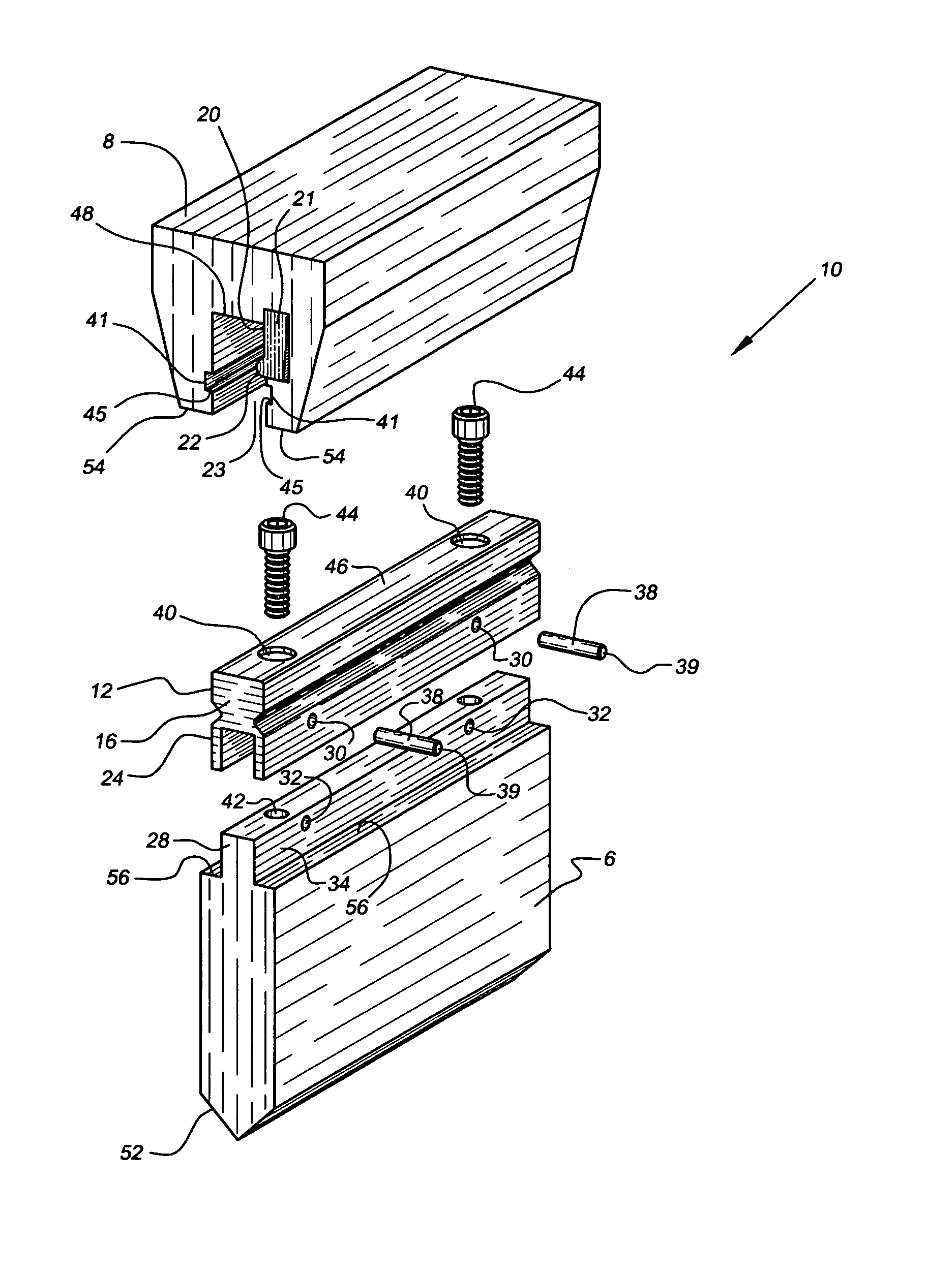
Figure 1 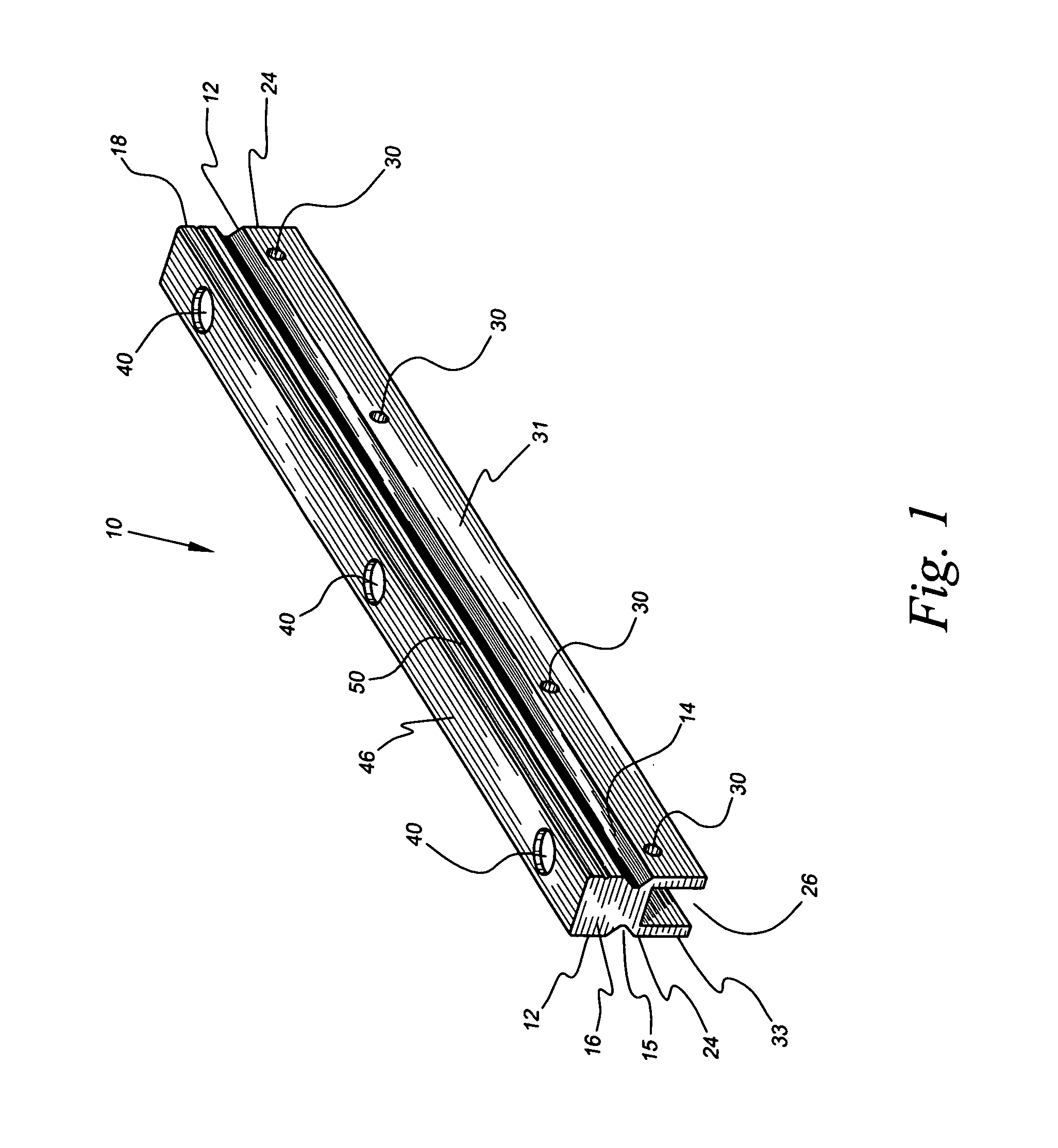
Figure 2 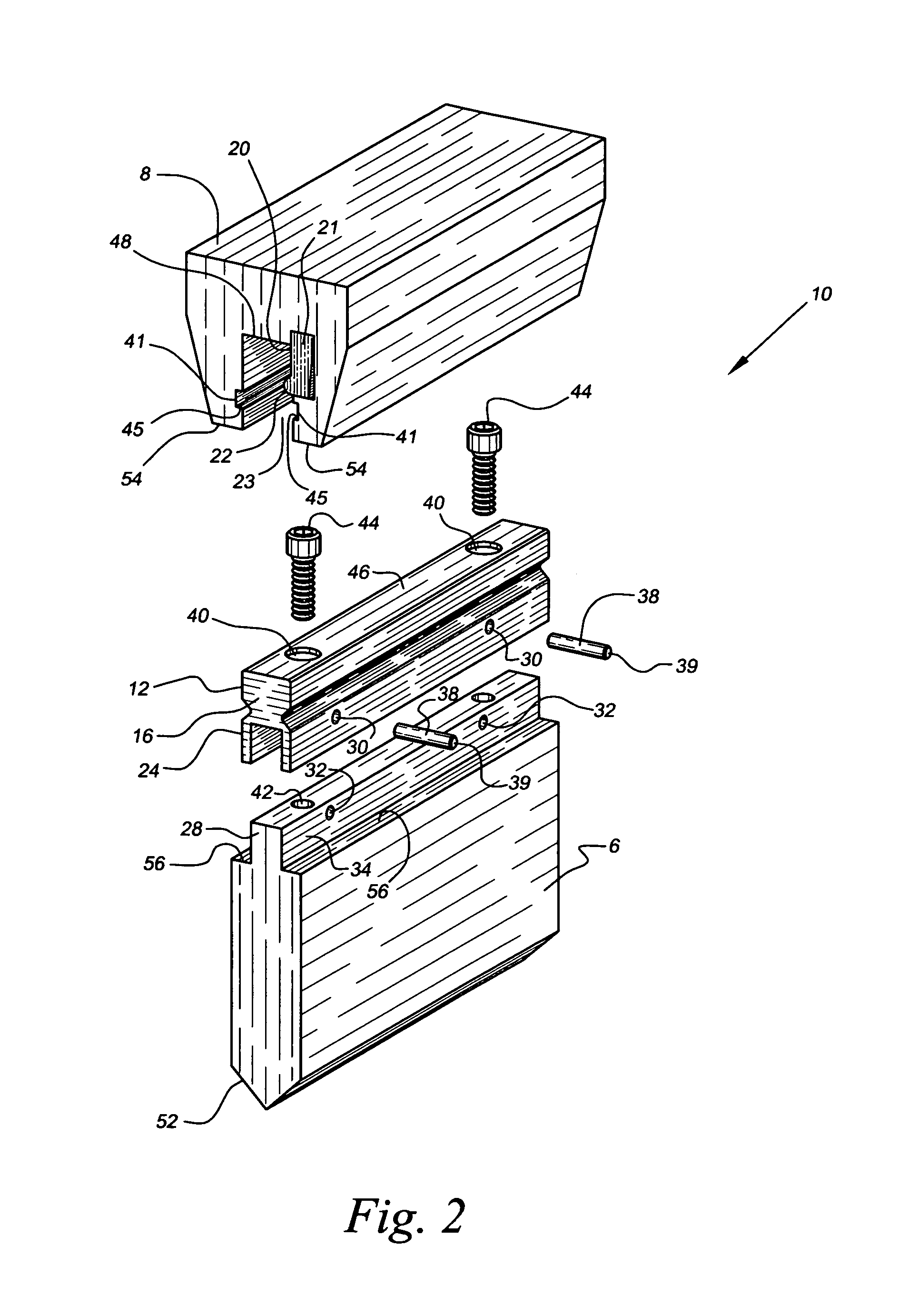
Figure 3
Abstract
Description
BACKGROUND OF THE INVENTION
[0001] 1. Field of the Invention
[0002] The present invention relates to press brakes for deforming workpieces into predetermined configurations, and more particularly, to devices and methods that secure a relatively old designed punch tool to a relatively new designed ram portion of a press brake.
[0003] 2. Background of the Prior Art
[0004] Press brake machines and their operative components that are utilized to deform workpieces into predetermined configurations are well known to those of ordinary skill in the art. Typically, a workpiece is disposed between a punch tool and a die, the press brake then forcibly urges the punch tool vertically downward into engagement with the workpiece until the workpiece congruently engages both the punch tool and the die thereby deforming the workpiece into a predetermined configuration consistent with the configurations of the punch tool and the die. An upper end of the punch tool is secured to a ram portion of the press bra...
Examples
Embodiment Construction
[0026]Referring now to drawings 1–9, a device for securing a typical punch tool 6 to a ram portion 8 of a press brake (not depicted) in accordance with the present invention is denoted as numeral10. The device 10 is a solid piece of cast metal, preferably tool steel, and includes an upper portion 12 having opposing front and back symmetrical outer recesses 14 and 15 extending longitudinally from a first end wall 16 to a second end wall 18, the outer recesses 14 and 15 being configured to snugly receive a corresponding inner wall 20 protuberance 22 of a clamp portion 21 of the ram portion 8 of the press brake. The device 10 snugly inserts, via the first or second end walls 16 and 18, into a cooperating recess 23 in the ram portion 8 such that the device 10, and the punch tool 6 removably attached thereto, are supported by the protuberance 22 of the clamp portion 21 of the ram portion 8 after the press brake grasps and “squeezes” the ram portion 8, thereby urging the protuberance 22 o...