
Seat belt retractor and pretensioner combination
a technology of safety belts and pretensioners, which is applied in the direction of belt retractors, vehicle safety belts, vehicle components, etc., can solve the problems of corresponding space requirements, inability to mount the belt retraction and pretensioner combination, and high cost of continuous bending of tubes to spiral shapes of channels, etc., to achieve simple and cost-effective assembly
Patent Information
- Authority / Receiving Office
- US · United States
- Patent Type
- Patents(United States)
- Current Assignee / Owner
- Publication Date
- 2010-06-15
Smart Images
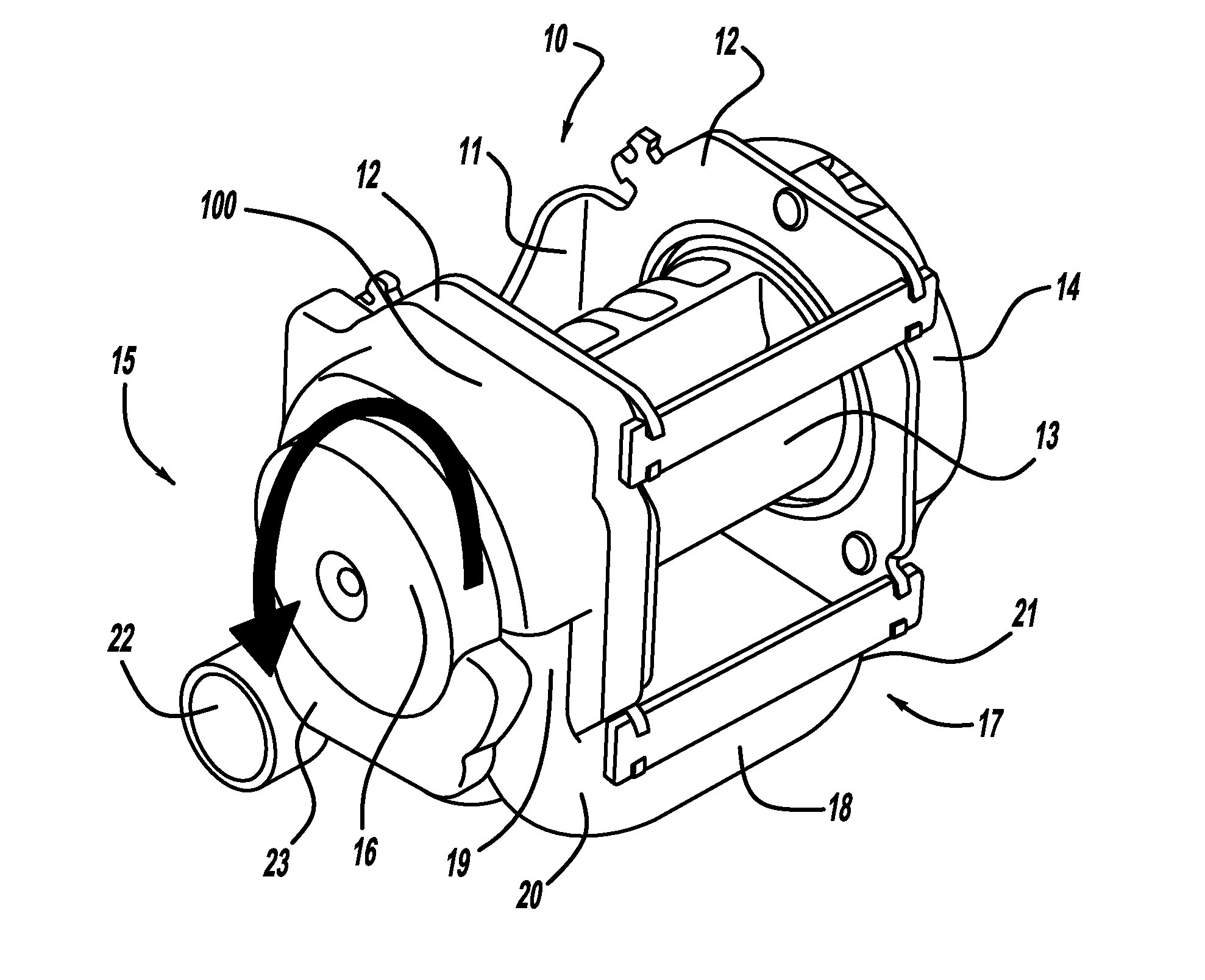
Figure 1 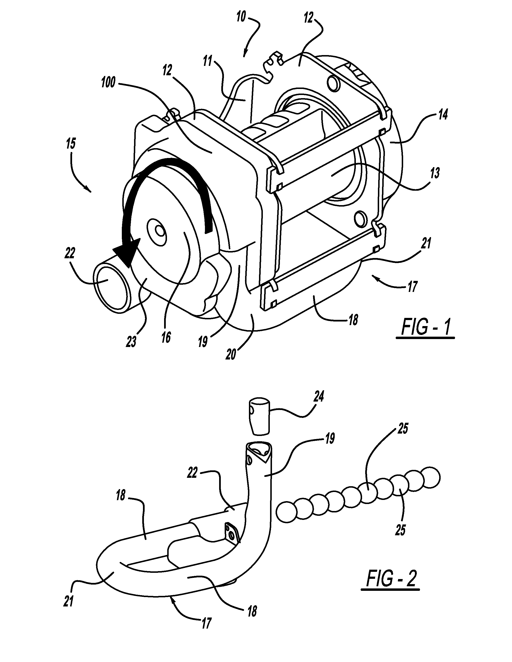
Figure 2 
Figure 3
Abstract
Description
CROSS REFERENCE TO RELATED APPLICATIONS
[0001] This application claims priority to PCT / EP2004 / 013562, filed Nov. 30, 2004 and to DE 103 56 206.0 filed Dec. 2, 2003.BACKGROUND
[0002] 1. Field of the Invention
[0003] The invention relates to a rotating retractor and pretensioner for a safety belt, especially in motor vehicles. The invention includes a belt retractor, the belt shaft of which supports the belt winding and rotates in the take-up direction of the safety belt when the tensioning drive coupled to the belt shaft is released. The belt shaft is associated with a drivewheel with recesses on the periphery thereof for accepting mass bodies acting as drive means, and the mass bodies are stored in a tube, which tangentially flows into the drivewheel, and the mass bodies are accelerated in the tube by means of a gas generator arranged at one end of the tube.
[0004] 2. Description of Related Art
[0005] A rotating retractor and pretensioner having the above features is described in U.S. Pat. No...
Examples
Embodiment Construction
[0020]The belt retractor 10 and pretensioner unit depicted in FIG. 1 includes a U-shaped belt retractor housing 11 and opposing housing sides 12, whereby the belt spool 13 is mounted in the housing arms 12. A sensing unit 14, which can comprise a seatbelt-sensitive and / or vehicle-sensitive locking unit for the belt shaft and the associated take-up spring, is arranged on the outside of the associated housing side 12 on one end of a belt spool 13 on the right end in the illustration of FIG. 1.
[0021]The drive side 15 of the associated retractor unit 10, includes a drivewheel 16 coupled to the projecting end of the belt spool 13 through the associated housing side 12 and is located opposite the sensing unit 14. The configuration and function of the drivewheel in cooperation with mass spheres 25 (see FIG. 2) serve as a drive means for pretensioning the seat belt, and is thoroughly presented in U.S. Pat. No. 5,881,962, which is herein incorporated by reference.
[0022]The mass spheres 25 ar...