
Substrate-guided imaging lens
a technology of optical systems and substrates, applied in the direction of optical light guides, polarising elements, instruments, etc., can solve the problems of state-of-the-art huds, inconvenient installation, unsafe use, etc., and achieve the effect of facilitating design and fabrication
Patent Information
- Authority / Receiving Office
- US · United States
- Patent Type
- Patents(United States)
- Current Assignee / Owner
- Publication Date
- 2011-08-16
Smart Images
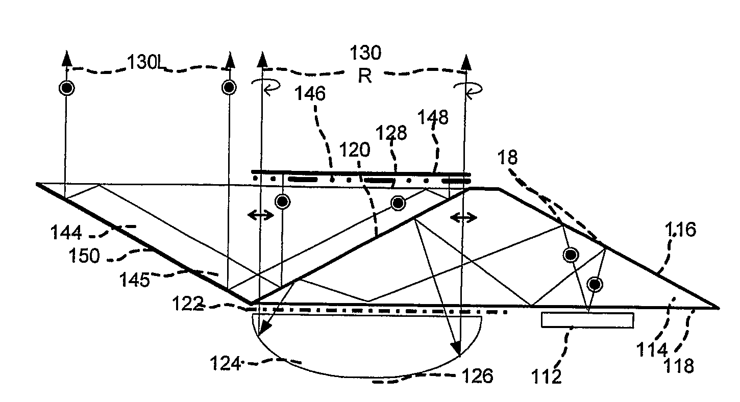
Figure 1 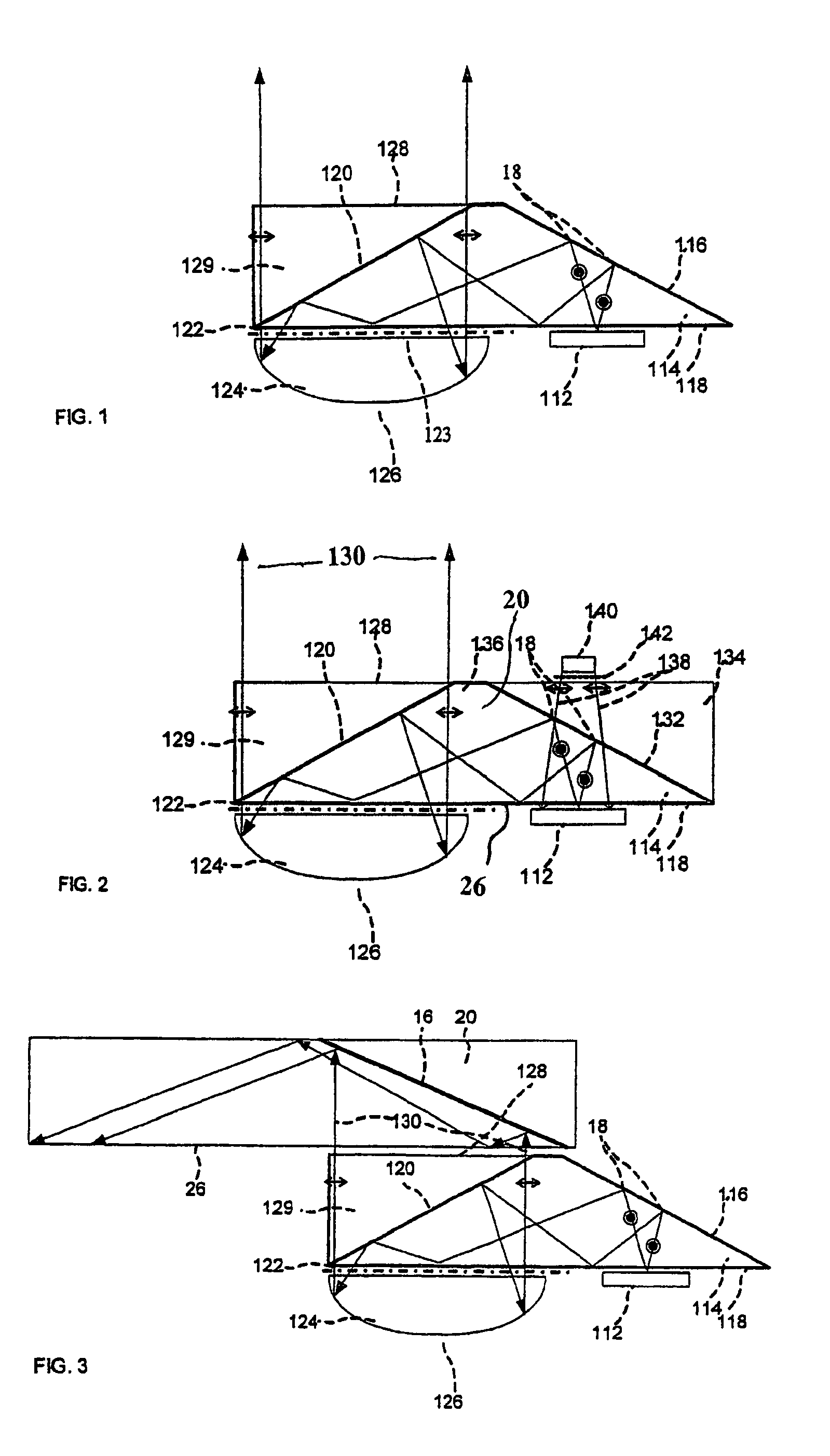
Figure 2 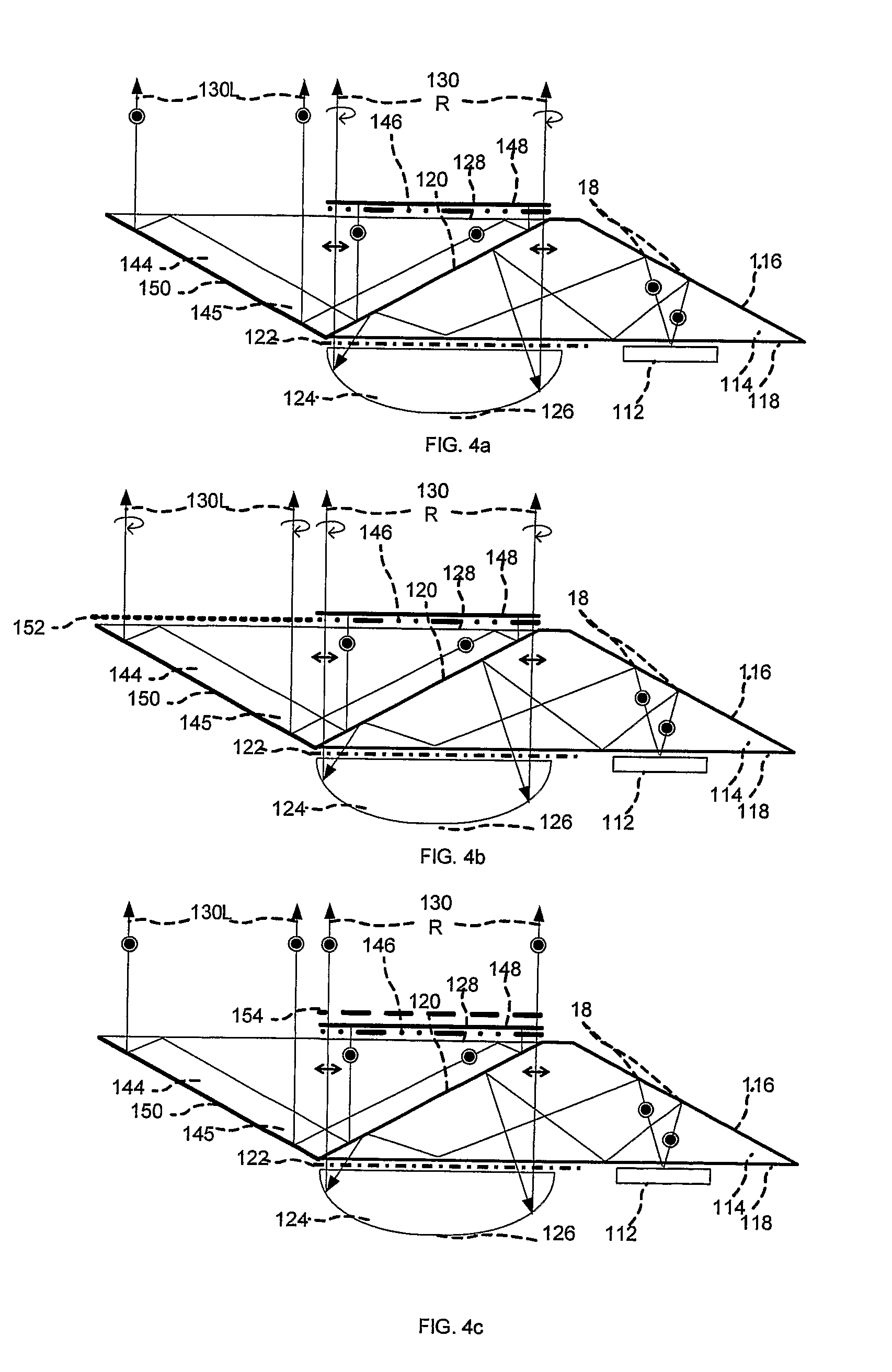
Figure 3
Abstract
Description
FIELD OF THE INVENTION
[0001] The present invention relates to substrate-guided optical systems, and in particular, to optical systems which include an arrangement of an reflecting optical element, a retardation plate and reflecting surfaces carried by a common light-transmissive substrate. Such a system is also referred to as a light-guide collimating element (LCE).
[0002] The invention can be implemented to advantage in a large number of imaging applications, such as head-mounted and head-up displays, cellular phones, compact displays, 3-D displays, compact beam expanders as well as non-imaging applications such as flat-panel indicators, compact illuminators and scanners.BACKGROUND OF THE INVENTION
[0003] One of the important applications for compact optical elements is in head-mounted displays wherein an optical module serves both as an reflecting optical element and a combiner, in which a two-dimensional display is imaged to infinity and reflected into the eye of an observer. The disp...
Examples
Embodiment Construction
[0048]A superior method of designing lenses more compact than the prior art lenses having the required planar shape while still maintaining the desired optical properties of the system according to the present invention, will now be described.
[0049]This method, which achieves these two seemingly contradictory requirements, and which exploits the fact that in most microdisplay light sources, like LCDs or LCOS, the light is linearly polarized, is illustrated in FIG. 1. As illustrated, the s-polarized input light waves 18 from the display light source 112 are coupled into the substrate 114 by the first reflecting surface 116. Following total internal reflection off the lower surface 118 of the substrate, the waves are reflected off a polarizing beamsplitter 120 and coupled out of the substrate. The waves then pass through a quarter-wavelength retardation plate 122 and a transparent surface 123, are then collimated by a reflecting optical element 124, e.g., a lens, at its reflecting sur...