
Polarizing optical system
a polarizing optical and optical system technology, applied in the direction of polarising elements, optical elements, instruments, etc., can solve the problems of inconvenient installation, inconvenient use, and inconvenient use of combiner-projector hud systems, so as to facilitate design and fabrication, facilitate installation, and large emb values
Patent Information
- Authority / Receiving Office
- US · United States
- Patent Type
- Patents(United States)
- Current Assignee / Owner
- Publication Date
- 2018-08-14
Smart Images
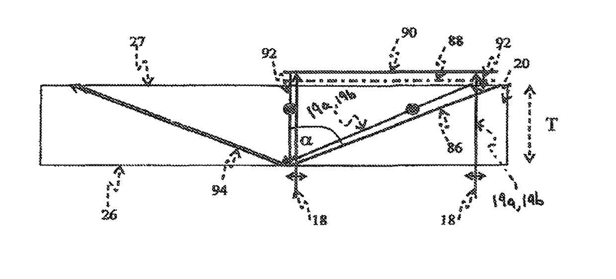
Figure 1 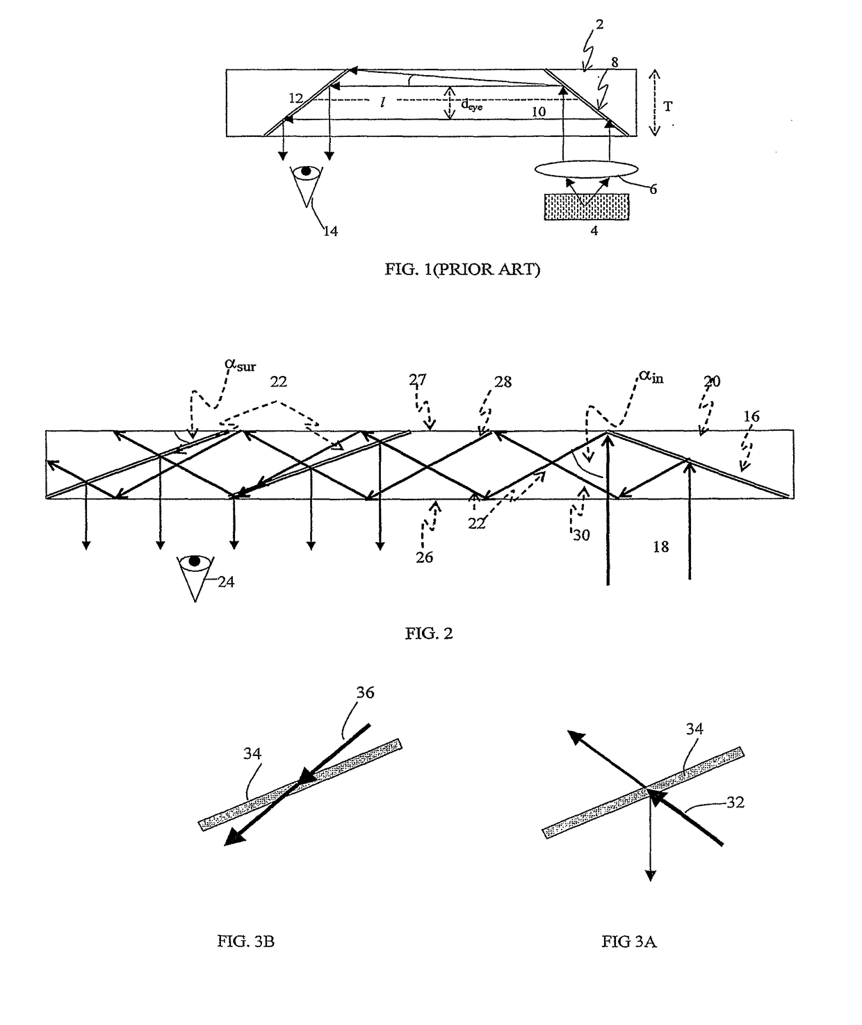
Figure 2 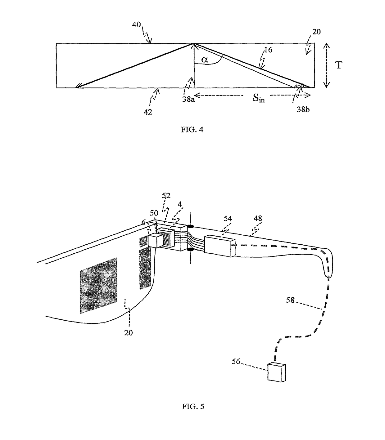
Figure 3
Abstract
Description
CROSS REFERENCE TO RELATED APPLICATIONS
[0001] This application is a divisional of application Ser. No. 12 / 092,818 filed May 6, 2008 for POLARIZING OPTICAL SYSTEM, now U.S. Pat. No. 9,551,880, granted Jan. 24, 2017.1. FIELD OF THE INVENTION
[0002] The present invention relates to substrate-guided optical devices, and more particularly, to devices which include a plurality of reflecting surfaces carried by a common light-transmissive substrate, also referred to as a light-guide.
[0003] The invention can be implemented to advantage in a large number of imaging applications, such as, for example, head-mounted and head-up displays, cellular phones, compact displays, 3-D displays, compact beam expanders as well as non-imaging applications such as flat-panel indicators, compact illuminators and scanners.DESCRIPTION OF RELATED ART
[0004] One of the important applications for compact optical elements is in head-mounted displays, wherein an optical module serves both as an imaging lens and a combine...
Examples
Embodiment Construction
[0032]FIG. 1 illustrates a conventional folding optics arrangement, wherein the substrate 2 is illuminated by a display source 4. The display is collimated by a collimating lens 6. The light from the display source 4 is coupled into substrate 2 by a first reflecting surface 8 in such a way that the main ray 10 is parallel to the substrate plane. A second reflecting surface 12 couples the light out of the substrate and into the eye of a viewer 14. Despite the compactness of this configuration, it suffers significant drawbacks; in particular, only a very limited POV can be affected. As shown in FIG. 1, the maximum allowed off-axis angle inside the substrate is:
[0033]αmax=arctan(T-deye2l),(1)
wherein T is the substrate thickness;
[0034]deye is the desired exit-pupil diameter, and
[0035]l is the distance between reflecting surfaces 8 and 12.
[0036]With angles higher than αmax the rays are reflected from the substrate surface before arriving at the reflecting surface 12. Hence, the reflect...