
Skin treating device
Patent Information
- Authority / Receiving Office
- US · United States
- Current Assignee / Owner
- Publication Date
- 2013-09-24
Smart Images
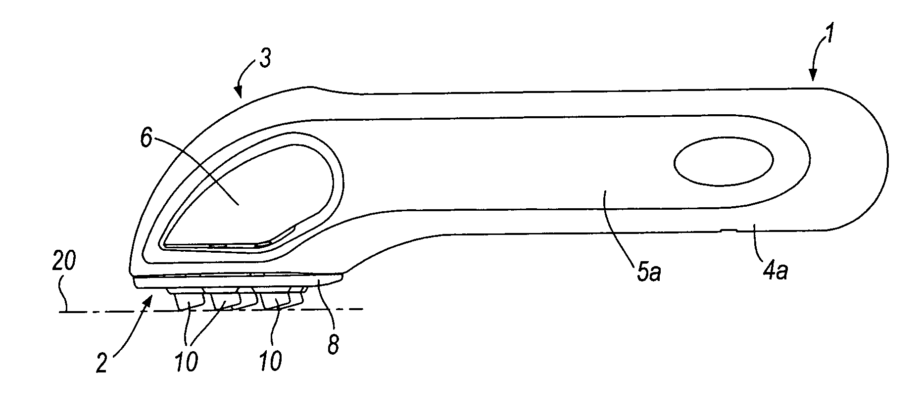
Figure 1 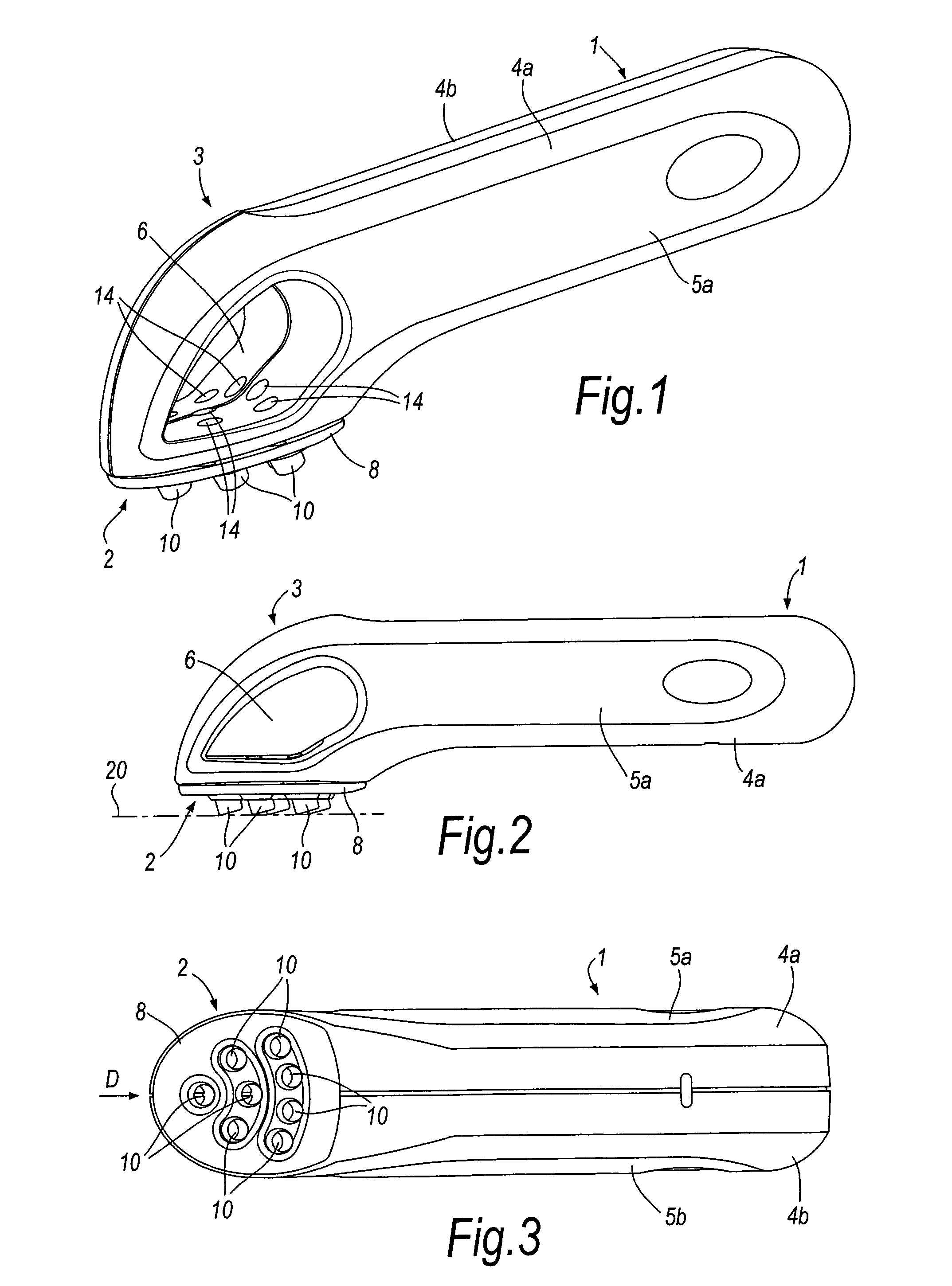
Figure 2 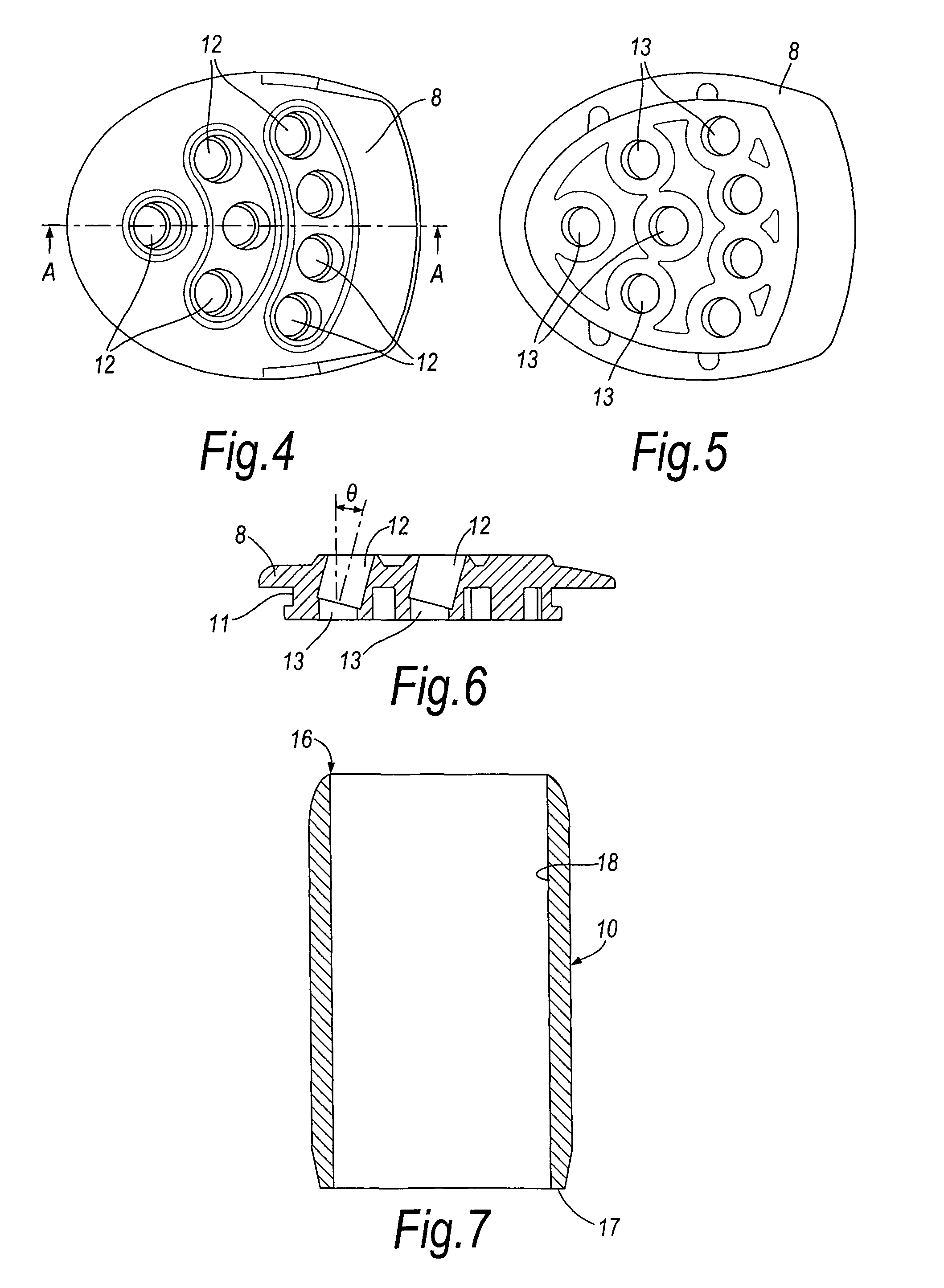
Figure 3
Abstract
Description
CROSS-REFERENCE TO RELATED APPLICATIONS
[0001] This application claims the benefit of International Application No. PCT / GB2009 / 002314, filed 28 Sep. 2009, which claims the benefit of GB 0817794.1, filed 29 Sep. 2008.FIELD OF THE INVENTION
[0002] This invention relates to a device for removing hard skin, particularly unsightly hard skin such as calluses, from the feet or hands.BACKGROUND OF THE INVENTION
[0003] Calluses are areas of thickened skin that may occur on the hands or feet and can be caused by persistent rubbing or uneven pressure, for example from ill-fitting shoes. They have a tendency to form over bony prominences and with regards the feet, they are most commonly found at the heel, the ball of the foot and the sides of the toes. On the hand they typically form on the underside of the fingers or on the palm. Calluses are often unsightly, and the thicker they are the more yellow they can look. With time, particularly thick calluses can become cracked and painful.
[0004] There are ...
Examples
Embodiment Construction
[0030]Illustrated in FIGS. 1 to 7 of the drawings is a device in the form of a hand tool for removing hard skin, such as calluses on the feet or hands of a user of the device. The device comprises an elongate handle 1 at one end of which is provided a working or cutting head 2. The device has a main body that includes the handle 1 and a cutting head support structure 3, this main body being assembled from two half shells 4a, 4b that are joined firmly and securely together along a longitudinal mid-plane of the device, such as by ultrasonic welding. To enhance comfort in use, the half shells 4a, 4b are provided with panels of softer material 5a, 5b conveniently moulded onto the half shells. The assembled main body includes a cavity 6 formed by a lateral through opening in the cutting head support structure 3, the purpose of which will be explained later.
[0031]The cutting head 2 is held fixed in position between the two half shells 4a, 4b when they are assembled and secured together, t...