
Tool for machining workpieces
Patent Information
- Authority / Receiving Office
- US · United States
- Current Assignee / Owner
- Publication Date
- 2014-08-05
Smart Images
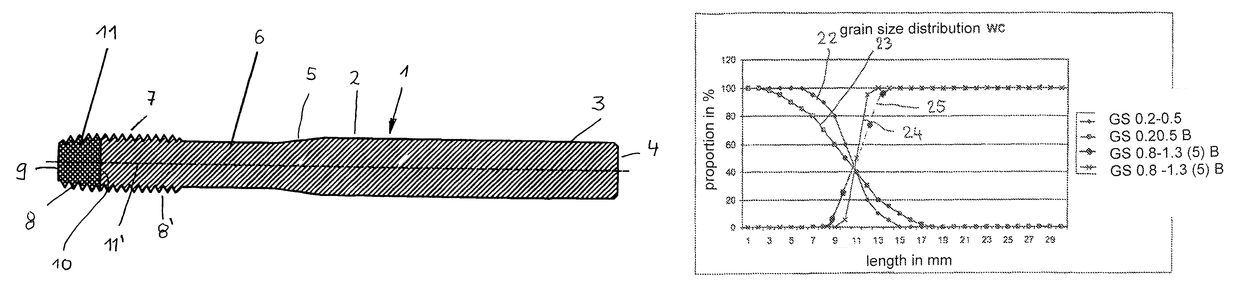
Figure 1 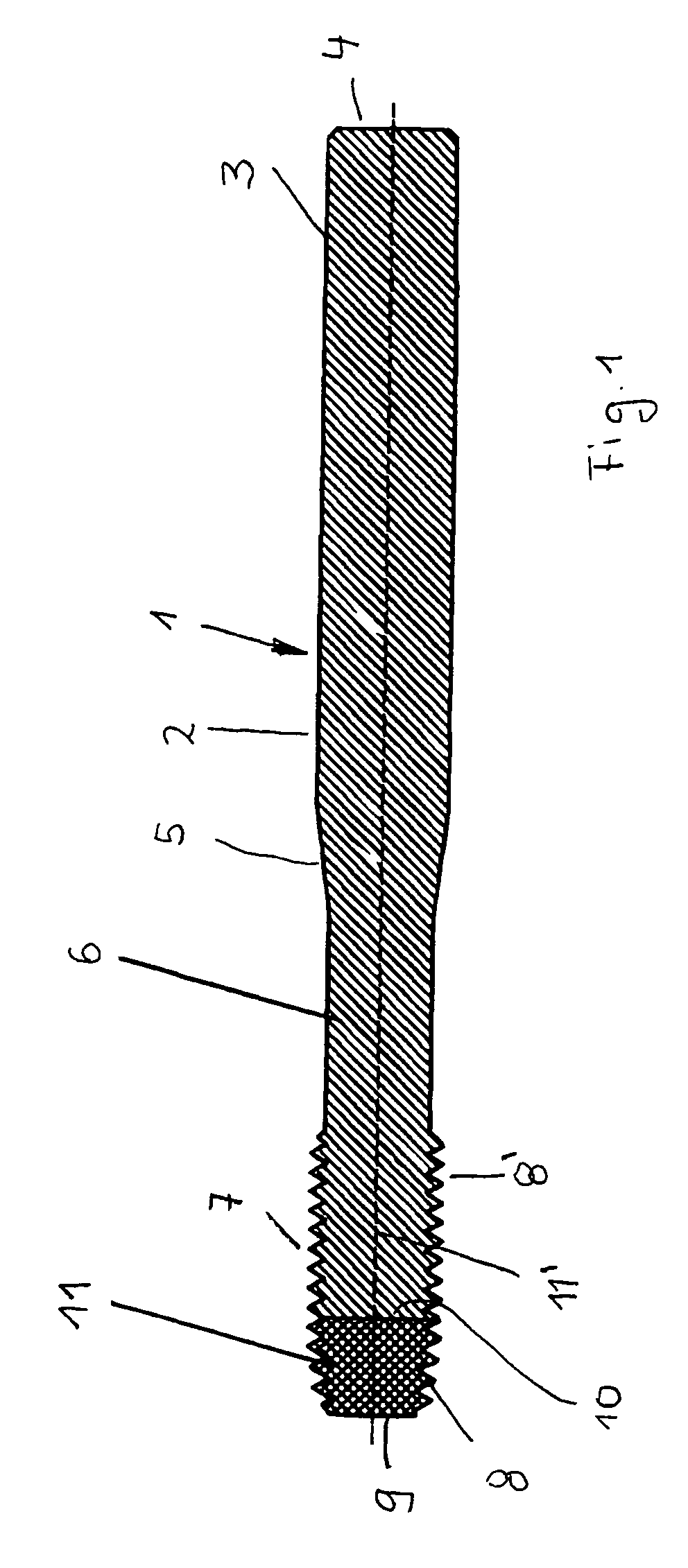
Figure 2 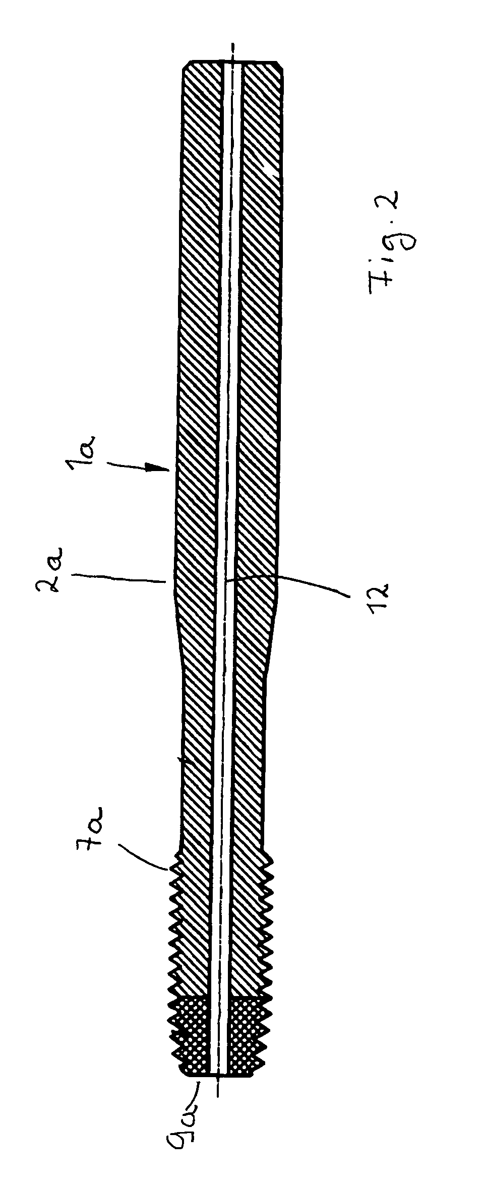
Figure 3
Abstract
Description
BACKGROUND OF THE INVENTION
[0001] The invention concerns a tool for machining workpieces, the tool comprising a clamping part and a working part that are comprised at least partially of a wear-resistant material and of a tough material, wherein both materials contain tungsten carbide.
[0002] In known tools of this kind, the working part and a clamping part are made of the same materials, i.e., a tough core material and a hard wear-resistant outer jacket. The manufacture of such workpieces is complex and expensive. Moreover, the different materials are used also at locations where they are not even required.
[0003] The invention has the object to configure such a tool in such a way that it can be configured in a simple and inexpensive way while it provides ing high wear resistance of the working part and satisfactory elasticity of the clamping part.SUMMARY OF THE INVENTION
[0004] This object is solved for a tool of the aforementioned kind in accordance with the invention in that the working...
Examples
Embodiment Construction
[0017]The tools illustrated in FIGS. 1 to 3 are thread formers that serve for manufacturing inner threads without cutting.
[0018]The thread former 1 according to FIG. 1 has a clamping part 2 that has a cylindrical shaft 3 with which it can be clamped in a tool receptacle. At the shaft end 4, the shaft 3 can be provided with a profiling (not illustrated) to provide an anti-rotation clamping action. The shaft 3 extends across somewhat more than half the tool length in the embodiment and passes by means of a conically tapering intermediate section 5 into a preferably cylindrical neck section 6 of the clamping part 2. The neck section 6 connects the intermediate section 5 with a working part 7. It has a first cut section 11 and a guide section 11′. The first cut section 11 has cutting edges 8 whose diameter increases in the direction of the guide section 11′ that has cutting edges 8′ with constant diameter. The end face 9 of the first cut section 11 is planar and extends perpendicularly ...