
Network relay device and control method thereof
a network relay and relay technology, applied in data switching networks, instruments, frequency-division multiplexes, etc., to achieve the effect of reducing false detection of failures
Patent Information
- Authority / Receiving Office
- US · United States
- Patent Type
- Patents(United States)
- Current Assignee / Owner
- Publication Date
- 2014-08-05
- Estimated Expiration
- Not applicable · inactive patent
Smart Images
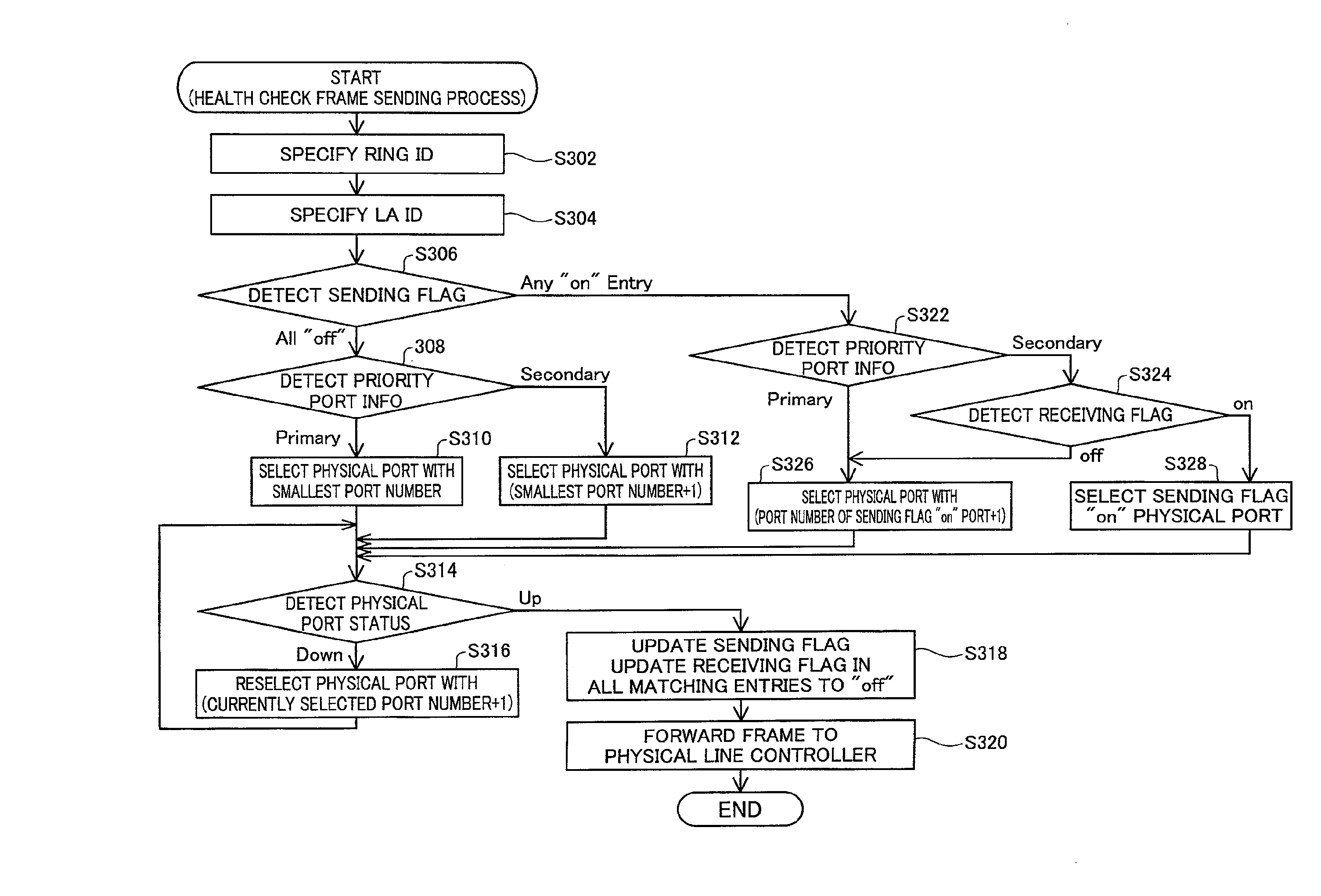
Figure 1 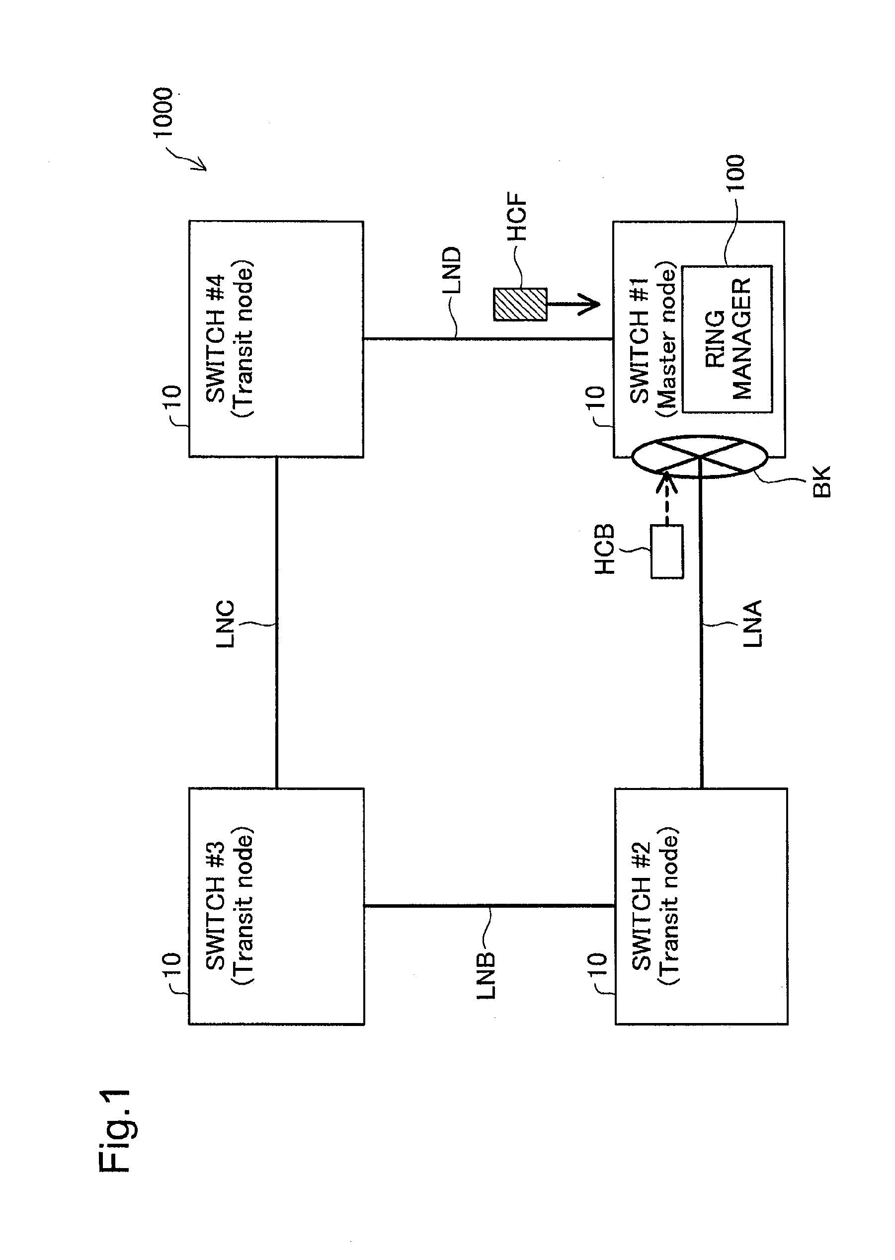
Figure 2 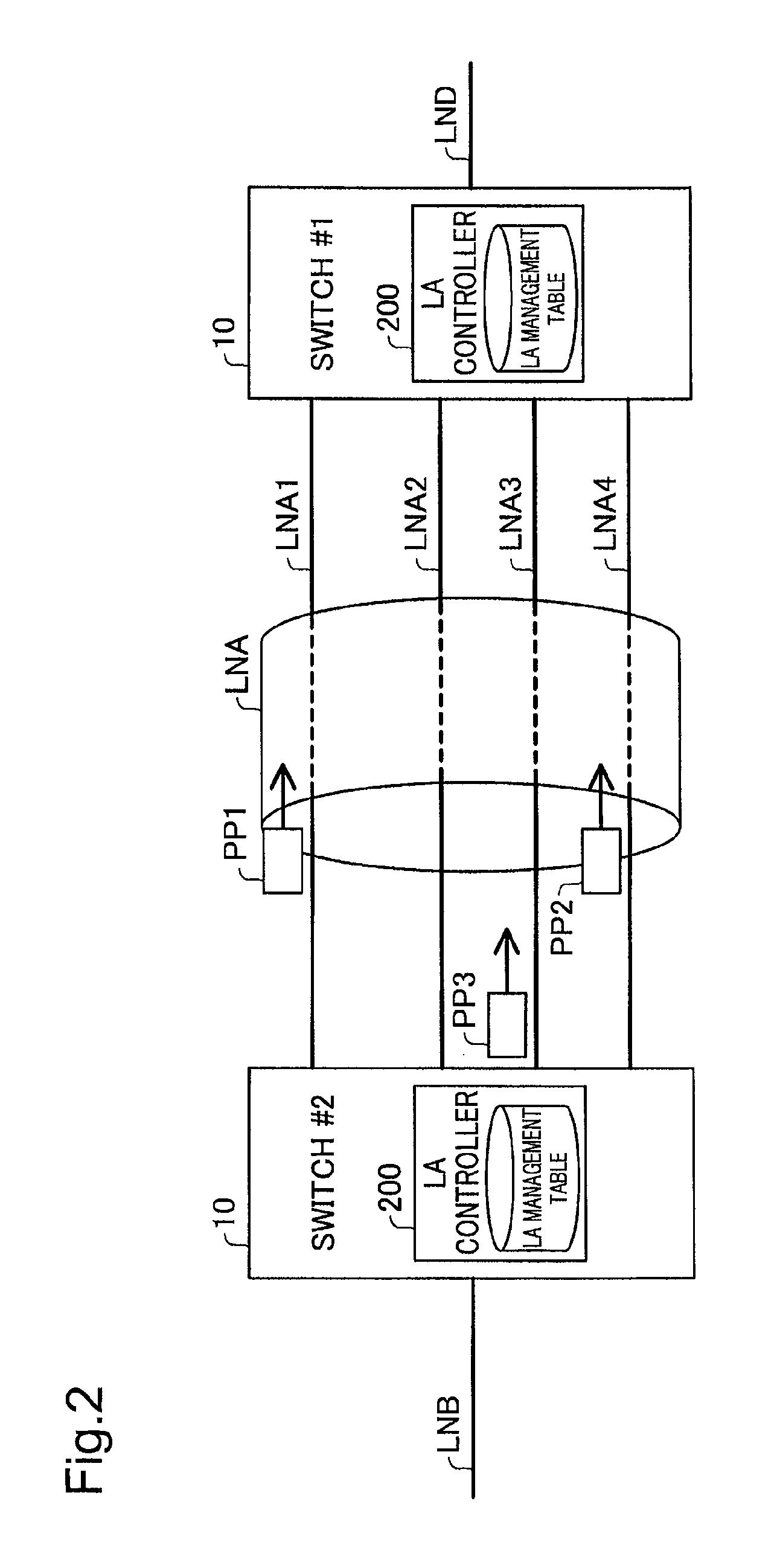
Figure 3
Abstract
Description
CROSS-REFERENCE TO RELATED APPLICATIONS
[0001] The present application claims priority to Japanese Patent Application No. 2011-153690 filed on Jul. 12, 2011, the disclosure of which is hereby incorporated by reference in its entirety.BACKGROUND OF THE INVENTION
[0002] 1. Field of the Invention
[0003] The present invention relates to a network relay device, and more specifically to detecting a failure occurring in a network, which a network relay device is connected with.
[0004] 2. Description of the Related Art
[0005] In the Ethernet (registered trademark)-based layer 2 network, Spanning Tree protocol (STP) according to the IEEE 802.1d standard has been known as the protocol to make the switches redundant. The STP causes control frames called BPDU (Bridge Protocol Data Unit) to be exchanged between the switches, so as to logically eliminate the loop structure of routing and check the status of a network, which the switches are connected to, such as the occurrence or non-occurrence of a failur...
Examples
first embodiment
B. First Embodiment
(B-1) System Configuration
[0094]FIG. 6 is a diagram illustrating the general configuration of the switch 10 according to one embodiment of the invention. The switch 10 includes a Ring manager 100, an LA Ring mapping table 110, an LA controller 200, a frame relay module 300, frame identification modules 310 and 320, a Health check frame controller 400 and a physical line controller 500. The Ring manager 100 and the LA Ring mapping table 110 are implemented by a CPU 15 and a memory 16. The LA controller 200, the frame relay module 300, the frame identification modules 310 and 320 and the Health check frame controller 400 are implemented by an ASIC (Application Specific Integrated Circuit) 17. The physical line controller 500 is constructed by a PHY chip.
[0095]The Ring manager 100 generates, sends and receives Health check frames according to the Ring protocol, in order to monitor the status of the network and change the communication path based on a change in networ...
second embodiment
C. Second Embodiment
[0183]Another configuration that employs different rules (first rule and second rule) to avoid using the same port as both the frame-sending port to send a Health check frame and the frame-receiving port to receive a Health check frame is described below as a second embodiment according to the invention. In the description and the illustrations of the second embodiment, the like constituents to those of the first embodiment are expressed by the like numerals to those of the first embodiment and are not specifically explained here.
[0184](C-1) System Configuration
[0185]FIG. 19 is a diagram illustrating the general configuration of a switch 10a according to the second embodiment. The difference from the first embodiment shown in FIG. 6 is only a Health check transmission controller 430a used in place of the Health check transmission controller 430. Otherwise the configuration and operations of the second embodiment are similar to those of the first embodiment. When ...
third embodiment
D. Third Embodiment
[0234]Another configuration that, in principle, prevents the state where the same port is used as both the frame-sending port to send a Health check frame and the frame-receiving port to receive a Health check frame, is described below as a third embodiment according to the invention. In the description and the illustrations of the third embodiment, the like constituents to those of the first embodiment are expressed by the like numerals to those of the first embodiment and are not specifically explained here.
[0235](D-1) System Configuration
[0236]FIG. 27 is a diagram illustrating the general configuration of a switch 10b according to the third embodiment. The difference from the first embodiment shown in FIG. 6 is only a Health check frame controller 400b used in place of the Health check frame controller 400. Otherwise the configuration and operations of the third embodiment are similar to those of the first embodiment.
[0237]The Health check frame controller 400b...