
Control device of permanent magnet synchronous motor for preventing irreversible demagnetization of permanent magnet and control system including the same
a technology of synchronous motor and control device, which is applied in the direction of electric generator control, dynamo-electric converter control, dynamo-electric gear control, etc., can solve the problems of not being able and no longer being able to generate torque from synchronous motor of permanent magnet, so as to prevent irreversible demagnetization of permanent magnet
Patent Information
- Authority / Receiving Office
- US · United States
- Patent Type
- Patents(United States)
- Current Assignee / Owner
- Publication Date
- 2015-06-09
Smart Images
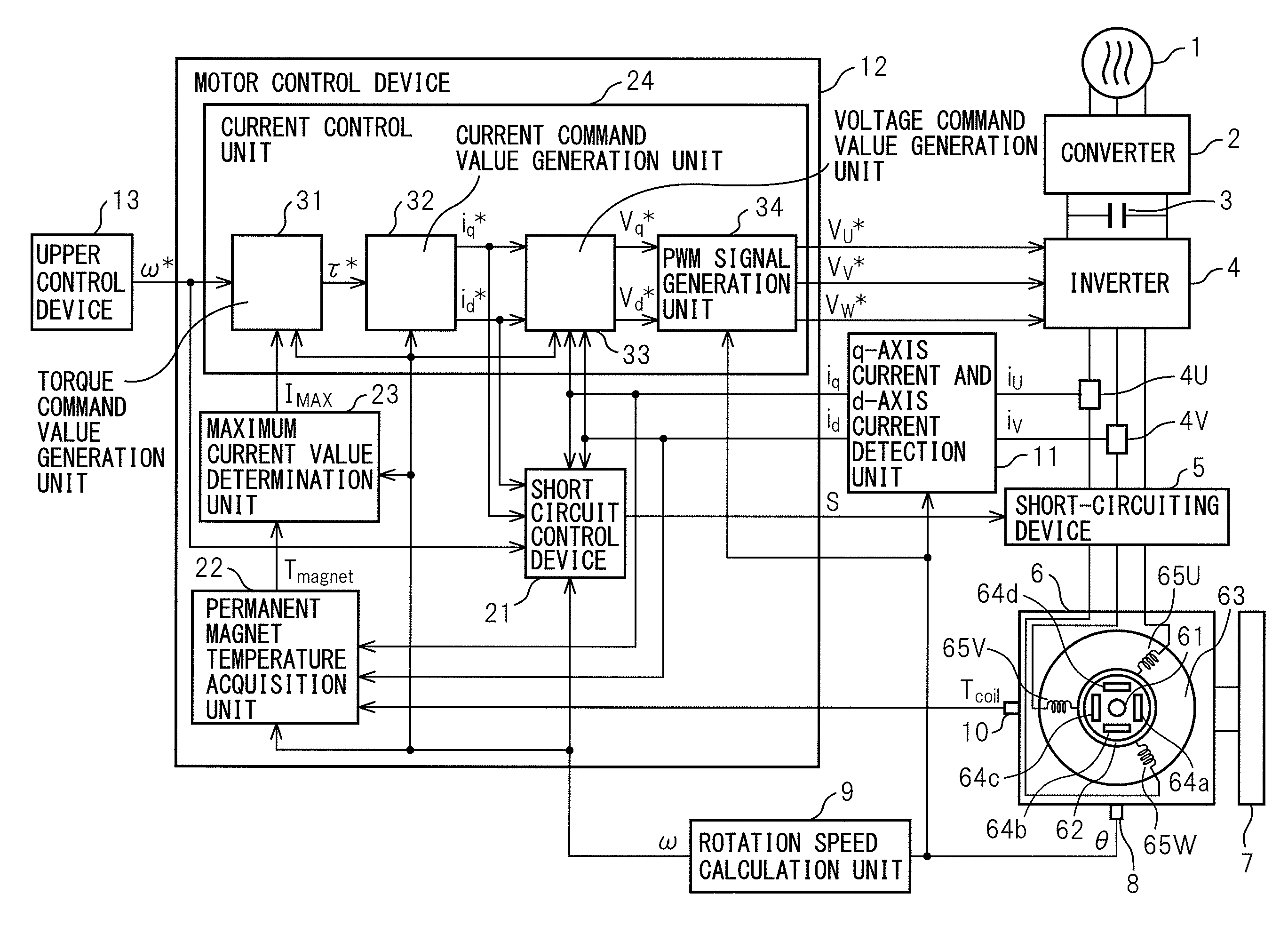
Figure 1 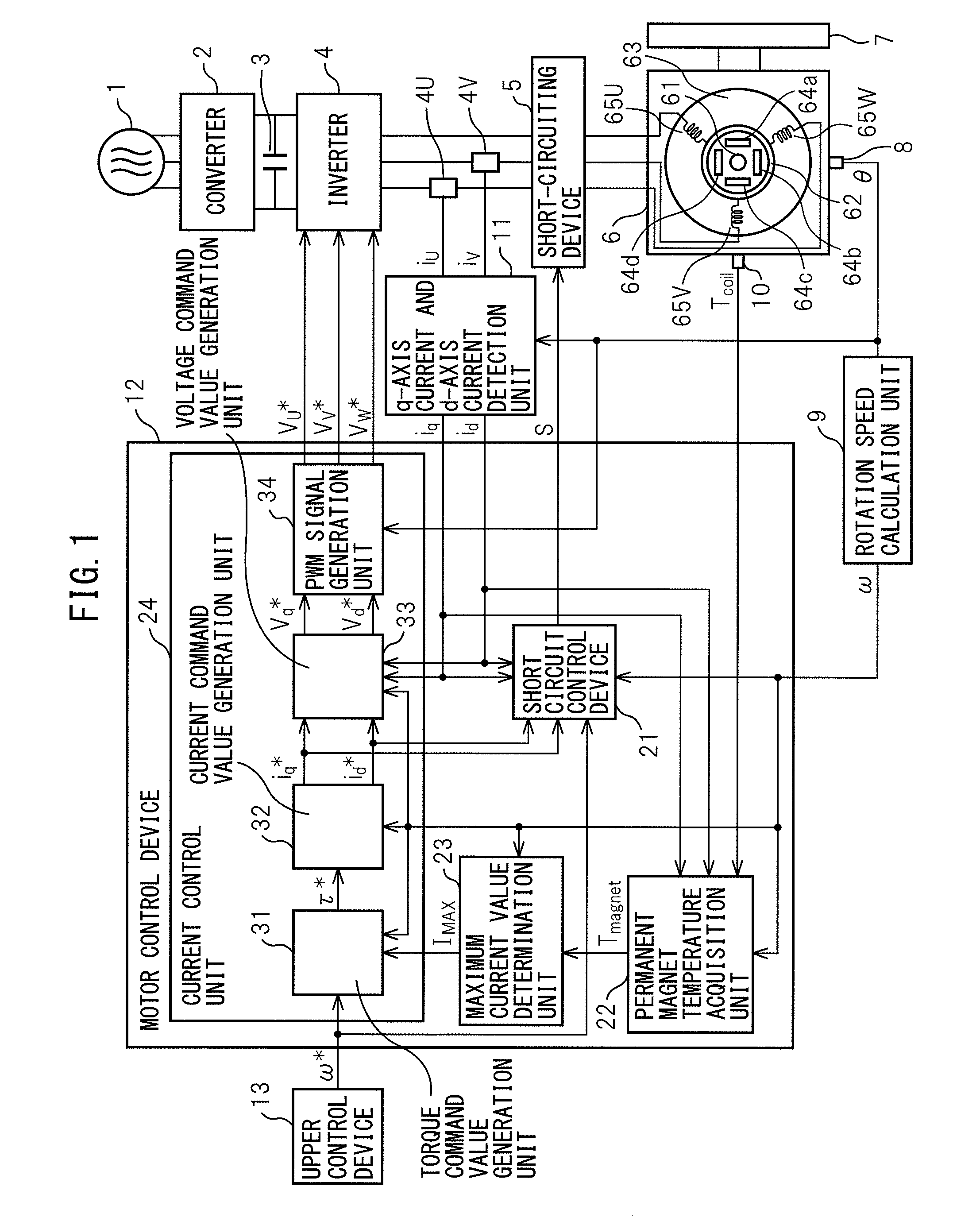
Figure 2 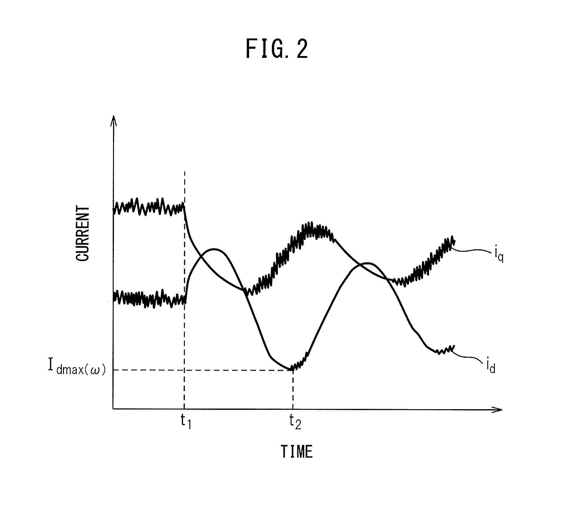
Figure 3
Abstract
Description
RELATED APPLICATIONS
[0001] The present application is based on, and claims priority from, Japanese Application Number 2012-196402, filed Sep. 5, 2012, the disclosure of which is hereby incorporated by reference herein in its entirety.BACKGROUND OF THE INVENTION
[0002] 1. Field of the Invention
[0003] The present invention relates to a control device of a permanent magnet synchronous motor for preventing irreversible demagnetization of a permanent magnet of a permanent magnet synchronous motor, and a control system including such a control device.
[0004] 2. Description of Related Art
[0005] When controlling a permanent magnet synchronous motor, there is a case where it is no longer possible for the permanent magnet synchronous motor to generate a torque quickly and stably due to irreversible demagnetization caused by a rise in permanent magnet temperature of a permanent magnet of the permanent magnet synchronous motor. Because of this, various kinds of motor control devices for preventing irr...
Examples
Embodiment Construction
[0030]Embodiments of the motor control device according to the present invention are explained with reference to the drawings. In the drawings, the same symbols are attached to the same components.
[0031]Referring to the drawings, FIG. 1 is a block diagram of a control system having a motor control device of an embodiment of the present invention. The control system illustrated in FIG. 1 has a three-phase alternating-current power source 1, a converter 2, a smoothing capacitor 3, an inverter 4, a short-circuiting device 5, a permanent magnet synchronous motor 6, a driven object 7, a rotation angle sensor 8, a rotation speed calculation unit 9, a coil temperature sensor 10, a q-axis current and d-axis current detection unit 11, a motor control device 12, and an upper control device 13.
[0032]The converter 2 consists of a plurality (six, in the case of three-phase alternating current) of rectifier diodes, for example, and converts alternating-current power supplied from the three-phase ...