
Rotor assembly, permanent magnet motor and compressor
A component and rotor technology, applied in the direction of electric components, magnetic circuit rotating parts, magnetic circuits, etc., can solve the problem of weakening of the anti-demagnetization ability of rotor permanent magnets, affecting the performance and reliability of motors and compressors, and affecting the service life of products, etc. question
Patent Information
- Authority / Receiving Office
- CN · China
- Current Assignee / Owner
- Publication Date
- 2022-07-15
Smart Images
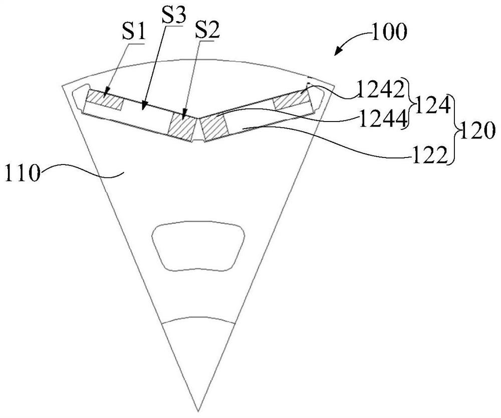
Figure 1 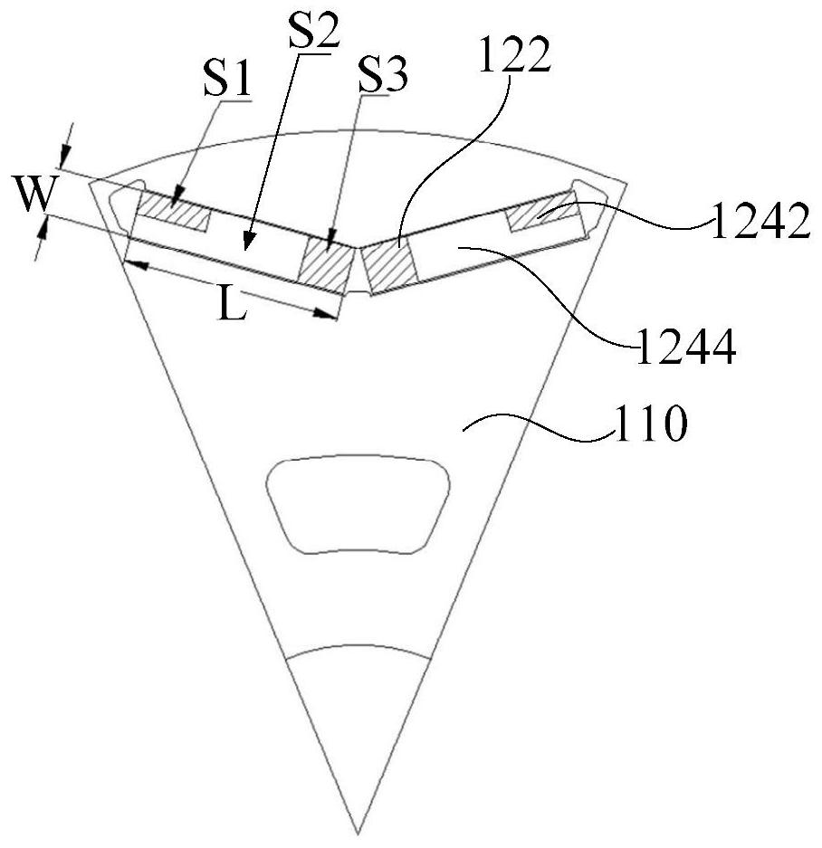
Figure 2 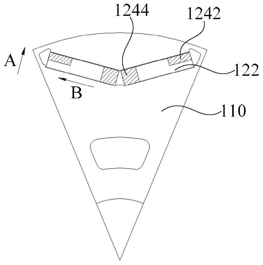
Figure 3
Abstract
Description
technical field
[0001] The invention relates to the technical field of compressors, in particular to a rotor assembly, a permanent magnet motor and a compressor. Background technique
[0002] At this stage, air-conditioning compressors at home and abroad basically use variable frequency motors, and variable frequency motors generally use permanent magnet motors. The excitation method of permanent magnet motor rotors is excited by permanent magnets. Due to the characteristics of high power density of permanent magnet motors and the need for cost reduction, the rotor The resistance to demagnetization of permanent magnets is weakened. When the permanent magnet is irreversibly demagnetized, it will affect the operating performance and reliability of the motor and compressor, and seriously affect the service life of the product.
[0003] Therefore, how to design a rotor assembly that can effectively solve the above-mentioned technical defects has become an urgent technical probl...
Examples
Embodiment 1
[0060] like figure 1 , figure 2 and image 3 As shown, the embodiment of the first aspect of the present invention provides a rotor assembly 100. The rotor assembly 100 includes: a rotor core 110, including a through hole; a permanent magnet 120, which is arranged in the through hole, and the permanent magnet 120 includes: a non-diffusion part 122; the diffusion part 124, the diffusion part 124 and at least part of the non-diffusion part 122 are arranged side by side in the first direction ( image 3 The middle direction A and the direction B show the first direction, specifically A is the thickness direction of the permanent magnet, and B is the width direction of the permanent magnet), and the first direction is perpendicular to the rotation axis of the rotor core 110; The mass ratio of heavy metal elements is greater than the mass ratio of heavy metal elements in the non-diffusion part 122 .
[0061] The present application defines a rotor assembly 100 for use in a perm...
Embodiment 2
[0067] like figure 1 , figure 2 and image 3 As shown, in the embodiment of the second aspect of the present invention, the rotor assembly 100 includes multiple groups of permanent magnets 120; two permanent magnets 120 are a group, and the two permanent magnets 120 in the same group are symmetrically arranged on both sides of the first plane , the rotation axis of the rotor core 110 and the diameter of the rotor core 110 are both in the first plane.
[0068] In this embodiment, the layout of the permanent magnets 120 on the rotor assembly 100 is defined. Specifically, each rotor assembly 100 is provided with a plurality of groups of permanent magnets 120 , and the plurality of groups of permanent magnets 120 are arranged around the axis of the rotor core 110 . Each group of permanent magnets 120 includes two permanent magnets 120, and the two permanent magnets 120 are symmetrically arranged on both sides of the first plane. The axis of the rotor iron core 110 and the dia...
Embodiment 3
[0074] like figure 1 , figure 2 and image 3 As shown, in the embodiment of the third aspect of the present invention, the diffusing portion 124 includes: a first diffusing portion 1242 disposed at an end of the non-diffusion portion 122 away from the first plane.
[0075] In this embodiment, the diffuser 124 includes a first diffuser 1242 . Specifically, the first diffusion part 1242 is located at one end of the non-diffusion part 122 away from the first plane, and the first diffusion part 1242 and a part of the non-diffusion part 122 are arranged side by side in the first direction. By arranging the first diffusion part 1242 , two anti-demagnetization regions can be formed at the left and right ends of the two permanent magnets 120 distributed in a V sub-shape.
[0076] This is because the mass ratio of heavy metal elements in the first diffusion part 1242 is greater than that in the non-diffusion part 122 . Therefore, the coercivity of the left and right anti-demagneti...